
Tel: +386 3 4900 800
http://radar-electronics.com
3702003B
Copyright 2016
Page 5
the side blind zone. Contact PRECO Electronics
®
support for more
information.
System Connections
Locate the vehicle’s ignition power wire and connect to the red wire on the
sensor harness. If it is necessary to extend the power wire on the supplied
harness, use 20AWG wire as a minimum. Locate the vehicle’s turn signal
wire that is associated with the turn signal on the side on which the sensor is
being installed, and connect to the blue wire.
(Be sure that the turn signal
wire selected activates ONLY when the turn signal is active. On some trucks
the daytime running lights and/or air brakes will activate the wires
connected to the turn signal lamp)
. Connect the black wire of the sensor
harness to vehicle ground.
Figure 4.
Wiring Connections
System Operation
The Side Defender
™
radar system has two different modes of operation
depending on if vehicle speed information is supplied to the system over the
J1939 CAN bus.
No Vehicle Speed Available
If vehicle speed is NOT available to the system, the Side Defender
™
system
will detect and report all objects in the sensor field of view.
Vehicle Speed is Available
If vehicle speed is available to the system, the sensor is capable of filtering
out stationary objects such as guardrails or concrete barriers, while still
detecting moving objects in the blind zone based on the speed. This feature
minimizes ‘nuisance alerts’ due to stationary objects in the detection zone,
e.g.
guardrails, signs, etc. This mode is optimized for on-highway blind zone
collision mitigation due to lane change or merging.
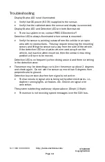
At speeds above 10mph (16kph), the system ignores stationary objects.
Models SDR8503 and SDL8503 will deactivate at speeds below 10mph
(16kph) and not report on any objects. Models SDR8504 & SDL8504 will
report all objects when below 10mph (16kph) and not ignore stationary
objects.