


2
The
Anti-Smoking Alarm
High Tech Solutions for the New Millennium
I N S T A L L A T I O N G U I D E
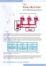
7. Connect the cables from the controller back-plate printed circuit board as shown above. If you are not installing the maximum five
detectors to your system, remember to include shorting links between Terminal 'C' and whichever inputs (DI to D5) that you are not
using. Should you fail to do this, those particular zones will be a permanent fault condition, flashing yellow on the controller fascia.
8. Once you have connected all the detectors as shown above, and checked them thoroughly to ensure that they have been done
correctly, you are ready to set the sensitivity of each of the Detectors.The factory setting is 'High' and we would recommend that you
only change this if you are experiencing false alarms (see section on Siting Detectors) Each of the Detector printed circuit boards have
two selector switches (Shown below as Jumper 1 and Jumper 2) that can be removed by inserting the tab between finger and thumb
and removing them.The settings are shown in the table below.
9. Each of the detector heads may now be inserted into their bases.This is accomplished by offering them up and twisting them
clockwise until they locate and stop rotating in position.
10. Once the cabling is completed and checked, you can insert 4 'D' Cell batteries into the battery box located on the back-plate of the
controller. BE SURE TO OBSERVE THE CORRECT POLARITY! The batteries can then be held in place by means of the velcro strip
supplied. Re-fit the ribbon cable to the terminal printed circuit board, observing the correct polarity, and slide the front cover of the
controller over the back-plate until the locating pins snap into position.The installation is now complete!
SENSITIVITY
High
Medium/High
Medium/Low
Low
JUMPER1
ON
ON
OFF (Removed)
OFF (Removed)
JUMPER2
ON
OFF (Removed)
ON
OFF (Removed)


