background image

2-18 Installing Mainframe Options                          

Chapter 2

Installing the Mainframe

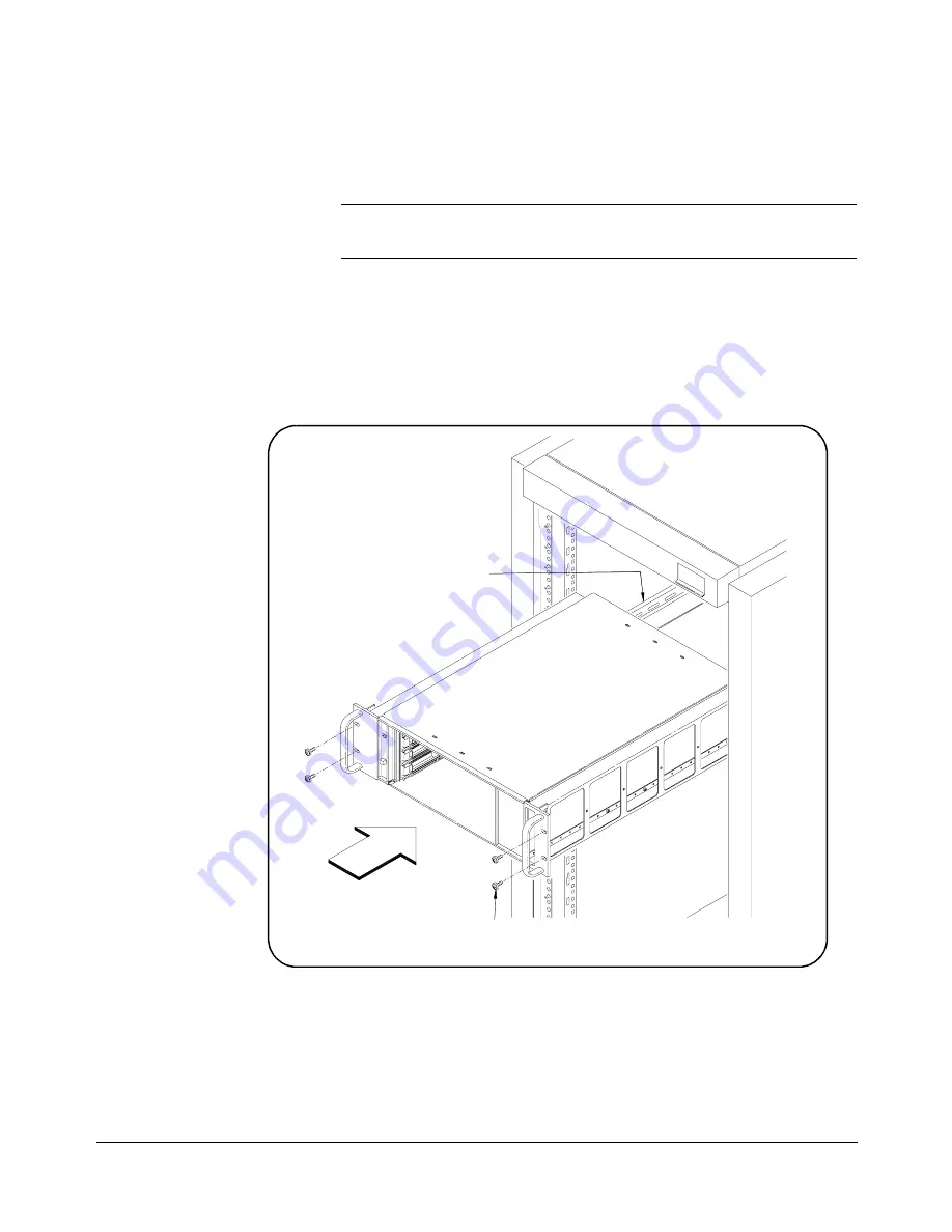
Install the Mainframe in the Rack Cabinet (Figure 2-17)

1  With one person on each side, lift the mainframe and slide the 

mainframe fully onto the Support Rails.

WARNING

To prevent possible injury during rack mounting, two people 
should lift the mainframe into the rack. 

2 Slide the mainframe into the rack until the Rack Mount Adapter 

flanges are against the rack’s front vertical columns. 

3 Secure the mainframe to the rack using the four adapter dress 

screws.  

Figure 2-15. Installing the Mainframe

Adapter Dress

Screws

Support

Rail

Содержание 1266

Страница 1: ...49 859 7139 info eads nadefense com sales eads nadefense com helpdesk eads nadefense com http www eads nadefense com PUBLICATION DATE May 23 2006 Copyright 2003 by EADS North America Defense Test and...

Страница 2: ......

Страница 3: ......

Страница 4: ......

Страница 5: ...formance to EADS ISO 9001 2000 processes For the specific terms of your standard warranty or optional extended warranty or service agreement contact your EADS North America Defense Test and Services I...

Страница 6: ...it is responsible for the operation of the goods purchased and should ensure that they are used properly and in accordance with this handbook and any other instructions provided by Seller EADS North...

Страница 7: ...nsion cord or a three prong two prong adapter This will defeat the protective feature of the third conductor in the power cord Maintenance and calibration procedures sometimes call for operation of th...

Страница 8: ...viii...

Страница 9: ...Installation Procedure 2 2 Rack Mounting Using Support Rail Kit 2 12 Parts List 2 12 Installation Procedure 2 12 Installing Intermodule Chassis Shields 2 20 Parts List 2 20 Installation Procedure 2 20...

Страница 10: ...otal Usable Power A 4 Peak and Dynamic Current A 4 Output Voltage A 4 Power Input A 5 Cooling Specifications A 5 Cooling Table A 6 Cooling Chart A 6 Safety Environmental Specifications A 6 Environment...

Страница 11: ...onsists of the 4 slot C size mainframe with front panel monitor protective bumpers and a carrying handle Optional filler panels and shields can be added to the Standard Configuration The Rack Mount Co...

Страница 12: ...Options Rack Mount Configuration Rack Mount Cable Adapter Kit Protective Bumpers Rack Slide Kit Right Hand Shown Support Rail Kit Right Hand Shown OR Bumpers Protective Carrying Handle Standard Config...

Страница 13: ...system cabinet the power cord need not be accessible since the cabinet must have its own disconnect device Some fault conditions require removal of AC power for recovery to occur See Chapter 3 Servici...

Страница 14: ...ent earth ground 1 Connect a 16 AWG 1 3 mm or larger wire to the PEM nut shown in Figure 1 2 The wire must be green with a yellow stripe or bare no insulation Use a M4 x 10 screw grounding lug and too...

Страница 15: ...slots 2 To prevent damage to VXI instruments do not install instruments unless the Power On Standby switch is in Standby position 3 Insert the instrument into the mainframe by aligning the instrument...

Страница 16: ...ze adapter allowing a B size module to be installed just like a C size Front Panel Features Figure 1 3 shows the 1266 Front Panel features and the table describes the features When the mainframe is co...

Страница 17: ...rect The backplane voltages and allowed variations are listed below Voltage Allowed Variation 5V 4 875V to 5 125V 12V 11 64V to 12 6V 12V 12 6V to 11 64V 24V 23 28V to 25 2V 24V 25 2V to 23 28V 5 2V 5...

Страница 18: ...1 8 Getting Started Chapter 1...

Страница 19: ...ing the Airflow Restricter Kit 2 22 NOTE Mainframe illustrations in this chapter may show empty mainframes However you may receive integrated pre configured VXI systems with VXI instruments modules al...

Страница 20: ...e are three main steps to rack mount the 1266 mainframe using the Option 04 Rack Mount Cable Route Adapter Kit and the Option 01 Rack Slide Kit Configure the Mainframe Set up Rack Cabinet Install the...

Страница 21: ...nframe Options 2 3 Chapter 2 Configure the Mainframe Remove Mainframe Items as applicable Figure 2 3 1 Remove the two protective bumpers Figure 2 1 Removing Mainframe Items Bumper from Each End Remove...

Страница 22: ...a handle to the RH Rack Mount Adapter using two 10 32 X 0 375 flat head screws NOTE The rack mount adapter without the opening is the left side LH Rack Mount Adapter and the rack mount adapter with t...

Страница 23: ...cessed Check the mass interconnect system manufacturer s instructions BEFORE attaching the adapters to the mainframe For easier installation place the screws in the openings before you begin attaching...

Страница 24: ...ve the Right Side RH Rack Slide Chassis Section from the Intermediate Section 5 Slide the Intermediate Section back into the Stationary Section NOTE Be sure to mark the chassis sections as RH or LH so...

Страница 25: ...Adapter using four 10 32 x 0 375 pan head screws 2 Connect the RH Rack Slide chassis section to the RH Rack Mount Adapter using four 10 32 x 0 375 pan head screws Figure 2 5 Connecting Chassis Sectio...

Страница 26: ...ions are the same 3 Slide two 10 32 Self Retained Nuts provided in the Rack Mount Cable Route Adapter Kit over the selected holes in the right hand front vertical column of the cabinet These nuts will...

Страница 27: ...et See Figure 2 10 for hole locations 2 Attach the RH Rack Slide Stationary Section to the right hand vertical column of the cabinet Use two 10 32 x 0 5 flat head screws at the front of the rack slide...

Страница 28: ...th one person on each side lift the mainframe and slide the Chassis Sections into the Intermediate Sections until the Chassis Sections lock into place 3 Slide the mainframe into the cabinet until the...

Страница 29: ...pter 1 Getting Started 2 Connect cable s to instrument front panel terminals as required 3 Route cables through the right side cable tray RH Rack Mount Adapter as required NOTE Cables should not be ro...

Страница 30: ...n steps to rack mount the 1266 mainframe using the Rack Mount Cable Route Adapter Kit Option 04 and the Support Rail Kit Option 05 Configure the Mainframe Set up Cabinet Racks Install the Mainframe Ta...

Страница 31: ...frame Options 2 13 Chapter 2 Configure the Mainframe Remove Mainframe Items as applicable Figure 2 12 1 Remove the two protective bumpers Figure 2 10 Removing Mainframe Items Bumper from Each End Remo...

Страница 32: ...the RH Rack Mount Adapter using two 10 32 X 0 375 flat head screws NOTE The rack mount adapter without the opening is the left side LH Rack Mount Adapter and the rack mount adapter with the cable rou...

Страница 33: ...ecessed Check the mass interconnect system manufacturer s instructions BEFORE attaching the adapters to the mainframe For easier installation place the screws in the openings before you begin attachin...

Страница 34: ...for the RH Rack Mount Adapter hole locations LH Rack Mount Adapter hole locations are the same 3 Slide two 10 32 Self Retained Nuts provided in the Rack Mount Cable Route Adapter Kit over the selected...

Страница 35: ...provided in the Support Rail Kit over the appropriate holes in the front and rear right hand vertical columns in the cabinet Repeat for the left hand vertical columns 4 Secure each Support Rail to th...

Страница 36: ...fully onto the Support Rails WARNING To prevent possible injury during rack mounting two people should lift the mainframe into the rack 2 Slide the mainframe into the rack until the Rack Mount Adapter...

Страница 37: ...ter 1 Getting Started 2 Connect cable s to instrument front panel terminals as required 3 Route cables through the right side cable tray RH Rack Mount Adapter as required NOTE Cables should not be rou...

Страница 38: ...sis shield guides Figure 2 19 Chassis shields should be installed on both sides of an instrument generating interference noise or installed on both sides of a sensitive instrument 1 Insert Grounding S...

Страница 39: ...nframe Options 2 21 Chapter 2 Figure 2 17 Installing the Grounding Springs and Chassis Shield Use a Small Screw Driver to Secure Spring Under SocketTab Shield VXI Module Guide Chassis Grounding Spring...

Страница 40: ...inframe on bench 2 As required remove filler panels and or installed VXI instruments from the mainframe 3 Follow the steps in Figure 2 20 to install the Airflow Restricter Figure 2 18 Installing the A...

Страница 41: ...ceable parts inside the mainframe Repair is limited to replacement of the components listed in Table 3 1 Replacement of these components must be performed at a static controlled workstation by trained...

Страница 42: ...itch is switched to ON If problem remains replace Power Supply Assembly Flashing Voltages Indicator Backplane voltage s may be incorrect Cycle mainframe Power switch Remove VXI instruments to ensure t...

Страница 43: ...Accessory Items For some component removal replacement you may need to remove mainframe accessory items as applicable see Figure 3 1 1 Remove the two protective bumpers Figure 3 1 Removing Mainframe...

Страница 44: ...e rack and place the mainframe at a static controlled workstation 3 Remove mainframe items as required See Removing Mainframe Items 4 Remove the ten M3x6 flat head screws five on each side of the main...

Страница 45: ...y Assembly to Racal Instruments for a remanufactured Power Supply Assembly See Table 3 1 for replacement part numbers Be sure to observe static free procedures when removing installing the Power Suppl...

Страница 46: ...Remove the mainframe cover See Removing the Mainframe Cover 5 Follow the steps in Figure 3 4 to disconnect the ribbon cable and to remove the Monitor Board 6 Reverse the steps in Figure 3 4 to instal...

Страница 47: ...uired See Removing Mainframe Accessory Items 3 Remove the Power Supply Assembly See Replacing the Power Supply Assembly 4 Remove the Fan Assembly by following the steps in Figure 3 5 5 Install the rep...

Страница 48: ...mainframe cover See Removing the Mainframe Cover 5 Remove the Front Panel Tapped Strip as shown in Figure 3 6 6 Install the replacement Front Panel Tapped Strip by reversing the steps in Figure 3 6 7...

Страница 49: ...er 3 Cleaning Instructions The only cleaning required for the 1266 mainframe is to wipe the exterior of the mainframe with a clean damp cloth and dry with a clean dry cloth Do not attempt to clean any...

Страница 50: ...3 10 Servicing the Mainframe Chapter 3 Notes...

Страница 51: ...6 Kg 19 lb without protective bumpers and 9 1 Kg 20 lb with bumpers Weight with four average VXI modules installed is 15 9 Kg 35 lb Maximum module weight is 3 5 Kg 7 7 lbs per slot to comply with sho...

Страница 52: ...nnector Shrouds Option 51 407870 051 Intermodule Chassis Shield Kit Option 52 407870 003 EMC Filler Panel 1 slot 407870 004 VXI Slot Filler Panel 1 slot 407870 005 1266 User Service Manual if ordered...

Страница 53: ...er applied to the mainframe and DC to installed VXI instruments Voltages Indicator Green all voltages on the VXI backplane are present Does not necessarily indicate that voltages are within the VXI sp...

Страница 54: ...utput current as defined by the VXIbus Specification 3 IMD Rated mainframe peak to peak dynamic current as defined in the VXIbus Specification by a current vs frequency curve 4 5V must have 1 0A minim...

Страница 55: ...fications apply at the backplane 0 55 o C Voltage Allowed Variation Ripple Noise DC Load Induced Ripple Noise Area Specification Comments Input Voltage Frequency 90 Vac min 140 Vac max 47 Hz min 440 H...

Страница 56: ...ode switchable on the front panel Same fan cools power supply and modules High Speed Fan Mode Maximum airflow all the time Variable Fan Speed Mode Fan speed changes between high and low as a function...

Страница 57: ...pment is protected against direct exposure to climatic conditions such as direct sunlight wind rain snow sleet and icing water spray or splash hoarfrost or dew typically indoors Pollution degree 2 Tem...

Страница 58: ...ame will turn on again Short to Ground Protection Short circuit behavior varies with the specific supply but in general recovery should occur when the short is removed This table summarizes short circ...

Страница 59: ...ed before the mainframe will turn on again Repair Diagnosis and troubleshooting through the front panel monitor MTTR Mean Time to Repair Item Time MTTR power supply assembly 20 min w mainframe and mod...

Страница 60: ...A 10 1266 Product Specifications Appendix A Notes...

Страница 61: ...t replaceable 3 1 peak and dynamic current A 4 positioning mainframe for cooling 1 3 power cords replacement 3 8 power input A 5 power requirements 1 3 power specifications A 3 power supply cooling 1...

Страница 62: ...compliance A 7 environmental A 6 A 7 front panel monitor A 3 general A 2 mainframe A 1 options and accessories A 2 output voltage A 4 peak and dynamic current A 4 power A 3 power input A 5 power suppl...

Страница 63: ...ne Number Purchasing Contact Phone Number 1 Describe in detail the problem and symptoms you are having Please include all set up details such as input output levels frequencies waveform details etc 2...

Страница 64: ......

Отзывы: