background image

Installation 

The following information is provided for use by your approved 
network supplier only.  The 

RA 

711 tel 

e can be either wall m 

mounted.  Wall mounting can be sur 

, flush or inset into the 

options  are  available,  as  defined 

the  "Electrical Connections 

Make sure that these are set correct! 

re finally fitting the unit 

emovable insert with your tele 

e number,  if desired. 

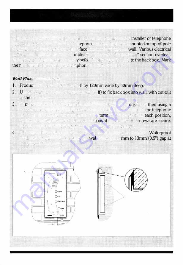
h Installation 

e hole in wall 285mm hig 

se size 8 or 10 screws with rawlplugs 

4 o 

at 

bottom. 

Co  nect the cabling, 

as 

detailed under "Electrical Connect" 

and 

4mm socket head key, through the 4 small holes in the front plate, 

fit 

unit  to  the  back box.  Start each  screw  by 

·ng  several times at 

continue turning each screw, several rotaf 

a time, until all 4 

To remove the telephone from the box reverse the procedure. 

Use  any  suitable  silicone  waterproofing  sealant 

(

such  as  Unibond 

.

Flexible Frame Sealant

to seal to the 

I, 

leaving a  12 

the bottom for drainage. 

I 2-13mm (0.5'') 

gap 

- 6 -

4 off size 8 or 

10 

screws 

at least 

25mm (I") 

long 

into Rawlplug type fixing: 

Содержание RA711/1011

Страница 1: ...USER GUIDE for RA711 1011 1012 1013 Vandal Resist Telephones PRESS TO CALL 111 EMERGENCY INFORMATION R AC AL AC O U STICS Publication No 552625 lss 2 December I992...

Страница 2: ...Contents...

Страница 3: ...ve to the meter qnd not spared to an extensioq ofa dires t exchange line or to next i ion on certain typ of PB cJhey are not suitable for party line instaljq jQJ lS 9r as extensions to a pay phgp RA71...

Страница 4: ...Provision to connect external extension bell 9 Provision to enable automatic clear down of call loop either fixed timeout or timeout after loss of incoming speech approx l Jnin Set by DIP switch on i...

Страница 5: ...Approved Facilities en connected to most compatible PBXs e However it cannot be guaranteed that p conditions of connection Any cases of instance to your local supplier of the instrument 3...

Страница 6: ...Operation RA711 1011 Ext No Area _ x 143 a a 8 Alarm behind panel 4...

Страница 7: ...Operation RA711 1012 RA711 1013 Ext No Area 999 D D _____ _ ____ ___ Alarm behind panel OPOLICE OFIRE OAMBULANCE 5...

Страница 8: ...5mm hig se size 8 or 10 screws with rawlplugs 4 o at bottom Co nect the cabling as detailed under Electrical Connect and 4mm socket head key through the 4 small holes in the front plate fit unit to th...

Страница 9: ...t to seal to the wall leaving a 12mm to 13mm 0 5 gap at the bottom for drainage 12 13mm 0 5 gap Wall Surface Installation 1 Fix the surface mounting back box to the wall with tut out at the bottom siz...

Страница 10: ...s are passed through relevant conduit and connect wired situations to the tag block on the instrument Connect the 9 volt approved D C power supply Pt No RAI 050 8 and ensure that it is switched on The...

Страница 11: ...ier The Terminal block mounted at the back of the unit is labelled as follows 1 2 bell 3 Not used 4 Line A extension bell pltig 431A 5 External induction loop for Hearing Aid 3 turns Im dia 7 8 0 volt...

Страница 12: ...o th frequencyA C type 15Hz 25Hz D C versions 2 and4 of the tag block Ensure that DIP switc internal bell capacitor if a master socket is 0 II Restriction Timeout used w I_f this facility is enabled S...

Отзывы: