background image

22


/ 30

User Manual

Rev. 1.0 - 18/06/12

DTUTT1K2HP1D

ELETTRONICA

  7.1.5   R.F. Combiner Menu

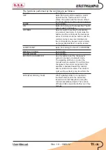
This  menu  contains  the  information  related  to  the  RF  part  of  the  complete 

transmitter. Here the user will find the most interesting parameters, like the overall 

emitted RF power and the reflected power.

Menu Line 

Description

Fwd 

Overall emitted RF power of the transmitter

Rfl 

Reflected RF power of the transmitter

Unbal 

Unbalancement RF power: sum of the power 

dissipated on the internal resistors due to 

unbalanecement in the RF modules

Rej.lT 

Temperature of the load resistors dissipating 

the unbalancement power

Exhaust 

Temperature of the exhaust air (top of the 

transmitter)

S.W.R. 

Standing Wave Ratio, calculated by the 

Control Unit on the basis of the measured 

forward and reflected power

(External) Fwd 

Forward power of an external transmitter 

(when configured for this function)

(External) Rfl 

Reflected power of an external transmitter 

(when configured for this function)

(External) Unbal 

Unbalancement power of an external 

transmitter (when configured for this 

function)

Main Exc 

Output power of the exciter currently on air 

(the one connected to the input of the RF 

modules)

Stdby Exc 

Output power of the exciter currently on the 

internal dummy load

Temp 

Status of the temperature alarm (sensor 

included in the combiner)

RF-Enb 

RF output enable: “On” means that the RF 

combiner unit is giving its permission for the 

regular operation of the transmitter

Aux Fan 

Switch for an auxiliary fan (not used in the 

current configurations)

SET1 

Status of the output “SET1”. See the 

Settings Menu

SET2 

Status of the output “SET2”

SET3 

Status of the output “SET3”

SET4 

Status of the output “SET4” 

Menu R.F. Combiner Screen

Содержание DTUTT1K2HP1D

Страница 1: ...DTUTT1K2HP1D USER MANUAL Manufactured by R V R ELETTRONICA S p A Italy ...

Страница 2: ...ed and bound in Italy No part of this manual may be reproduced memorized or transmitted in any form or by any means electronic or mechanic including photocopying recording or by any informa tion storage and retrieval system without written permission of the copyright owner File Name DTUTT1K2HP1D_ING_1 0 indb Version 1 0 Date 18 06 2012 Revision History Date Version Reason Editor 18 06 2012 1 0 Fir...

Страница 3: ...WRMS when used for its intended purpose is in compliance with the essential requirements and other relevant provisions of Directive 99 5 CE R TTE and therefore carries the CE mark The conformity assessment procedure referred in Article 10 and detailed in Annex III of Directive 99 5 EC has been followed The following harmonized standard have been applied Radio 3 2 EN 302 296 2 V 1 1 1 EMC 3 1b EN 3...

Страница 4: ...fication Frequency range UHF IV V band 470 to 862 MHz Nominal RF power 1250 WRMS DVB T Power supply voltage 400 Three phase 3F N Nominal exciting power about 5 W Consumption about 9 7 kW with red pattern Power factor 0 70 Weight 500 kg rack 20 kg module 140 kg Power supply ...

Страница 5: ... 2 Treatment of electric burns 2 4 General Description 3 4 1 Composition 3 5 Installation and Use 5 5 1 Installation 5 5 2 General First Start 5 6 Equipment Quick Reference 7 6 1 Exciter DTVCE 7 6 2 Amplifier Unit Control 9 6 3 First Start 12 6 4 Management of the exciters 15 6 5 Protections and alarms 17 7 Technical Description 18 7 1 Software Reference guide 18 ...

Страница 6: ...iv User Manual Rev 1 0 18 06 12 DTUTT1K2HP1D ELETTRONICA This page was intentionally left blank ...

Страница 7: ...iability for any errors or inaccuracies in this manual including the products and the software described herein R V R Elettronica S p A reserves the right to make changes to equipment design and or specifications and to this manual at any time without prior notice Notice concerning product intended purpose and use limitations This product is a radio transmitter suitable for frequency modulation au...

Страница 8: ...3 Figure 4 Figure 5 One rescuer give 2 quick rescue breaths after each 15 compressions Two rescuers one rescue breath after each 5 compressions Do not stop chest compressions while giving artificial breathing Call for medical help as soon as possible 3 1 2 If the victim is conscious Cover victim with a blanket Try to reassure the victim Loosen the victim s clothing and have him her lie down Call f...

Страница 9: ...FET as active components in the TV amplifying modules This chapter briefly describes the machine s main features 4 1 Composition The DTUTT1K2HP1D is made up 2 DTVCE010TU exciter 1 ATVHA5K0 amplifier 1 Control Unit 1 Combiner 5 250WRMS DVB T RF amplifier modules 2 Power supply unit carriages 1 Splitter Input RF 1 F1562 1 specifications The standard configuration of the DTUTT1K2HP1D foresees one 19 ...

Страница 10: ... the electrical and RF wiring As a rule the amplifier is supplied as a complete transmitter therefore the two TV exciters that it manages will be provided and connected a service exciter and a spare exciter Note This manual gives system level information about the DTUTT1K2HP1D Further details about the operation of the single components please refer to the relative manuals that are attached to the...

Страница 11: ...tter and before any other operation check that the equipments hasn t been damaged during transport and all the controls and connectors on the front and rear panels are in good condition To install the DTUTT1K2HP1D transmitter please refer to the relative technical dossier particularily about Mains supply connection RF connections Perform the connections following the instructions and schematics gi...

Страница 12: ...equired value indicated in technical dossier Note during the RF output power rising check the reflected power level on Control Unit to verify the antenna status The transmitter is now up and running at its nominal power level It is then possible to perform all the controls and verification that one thinks are necessary before putting it into operation Also you should check The equipment must be in...

Страница 13: ...u turn the encoder to the left counterclockwise the cursor moves rightwards if you turn it right the cursor moves leftwards it also permits to increase or diminish the parameters turning the encoder left diminishes the parameter turning it right increases it or to select an item from a list of options The rotation of encoder causes the lighting of the display in case it is not been lighted Push th...

Страница 14: ...ange the value from 0 to 9 so the frequency channel had a precision of 1 Hz Selecting OK this setting is stored otherwise selecting ESC each variation is ignored and you return in the previous menu To adjust the desired working power do the following operations Select Power SET menu rotate the encoder and then press it to enter in the submenu Select the POWER field reading and adjustment of delive...

Страница 15: ...r Unit Control The operator controls and checks the status of the DTUTT1K2HP1D by means of the control unit Two control groups are present on this unit LCD and scroll buttons Buttons selector switches and LEDs Analogue instrument and rotary selector switch Default Screen ...

Страница 16: ... value of a parameter being modified When the operator is not using the various buttons to navigate the LCD displays the preset screenful that shows the overall status of the machine s modules The control unit acquires every second the status of the other modules by means of a COM serial bus The activity at the bus is signalled by the BUS INT LEDs on the unit s panel As indicated on the preset scr...

Страница 17: ...ited and the commands may be given only remotely via the parallel interface or via the remote control software ALARM RESET Button for zeroing the FAULT or WARNING alarms NOMINAL POWER Not available POWER LOWER Not available EXCITER CHANGEOVER Use this button to set the changeover system in manual or automatic mode The signaling LED turns on when the manual mode is selected On performing a changeov...

Страница 18: ... are used when the transmitter is connected to a 1 1 system The SET outputs may also be connected to these quantities 6 3 First Start This section describes the procedure for powering on the machine the first time For simplicity ssake theautomaticcontrolcapacitiesoftheexcitersaretemporarilydisabled Refer to chapter 5 4 that provides the instructions for turning on the DTUTT1K2HP1D in the various c...

Страница 19: ...ment for the exciters changeover is disabled The MANUAL LED must be on otherwise press the key again Set the parameters of the control unit The control unit communicates the nominal power and reduced power values to the RF modules It also handles the coaxial relays so that the on air exciter is the desired one and sets the exciter to ON mode Set the exciters Adhere to the instructions of the excit...

Страница 20: ...n click the ESC button The display shows the screenful for selecting the menus Click the arrow keys until the cursor highlights the line associated with the Setting menu Click OK the software will show the associated screenful on the display When inside this menu it is advisable to check the date and time lines and update them if necessary Note the date and time are used only for marking the event...

Страница 21: ...t click the EXCITER CHANGEOVER button and check that the LED turns off In operation of the DTUTT1K2HP1D automatism state the behavior of the machine will be different In this chapter are described the different cases In function of the state of the DTUTT1K2HP1D automatism the behaviour of the machine will be various In this chapter are described the different cases 6 4 1 Start up from power on wit...

Страница 22: ... it is capable of supplying the required power then the two exciters are changed over Instead if the alternative exciter is not good no changeover takes place the control unit commands the mute RF of the exciter to Dummy Load it waits 120 s and repeats the attempt This procedure is repeated indefinitely until one of the two exciters is considered to be good During the whole length of time during w...

Страница 23: ...el the apparatus airs the one that had been present when the machine was turned off after the evaluation time has expired 6 5 Protections and alarms The DTUTT1K2HP1D contains a complete protection and alarms system both at the individual modules level and at the control unit level The modules are fitted with a micro processor based system that manages any malfunctions locally The associated inform...

Страница 24: ... any input in its different lines Menu Line Description Timer Indication of the start and stop times of the automatic power reduction feature see Settings menu Control Unit Status of the control unit Off or On and indication of the exciter actually connected to the amplifier Exct 1 or Exct 2 Power Supply Status of the power supply cart Off or On R F Combiner Status of the RF combiner Off or On R F...

Страница 25: ...mbiner Status of the RF combiner R F Units Status of the RF power amplifiers Alarms Summary of the occured alarms Service Service menu for the switching on off of the modules Settings Setting of the parameters i e Power levels Exciters Parameters of the exciters i e output power on air exciter Info Information concerning the configuration of the DTUTT1K2HP1D Release Information concerning the hard...

Страница 26: ...nput status Reserve 1 JP8 2 parallel interface Reserve 2 Input status Reserve 2 JP8 3 Reserve 3 Input status Reserve 3 JP8 4 Reserve 4 Input status Reserve 4 JP8 5 Relay Exc Exciters exchange relay status Off exciter 1 on air Exc 1 Mute Exciter 1 interlock status Off RF power enabled Exc 2 Mute Exciter 2 interlock status Off RF power enabled Audio Alarm Output Audio Alarm status JP47 1 Exc s Mains...

Страница 27: ...hin the functioning range of the unit and that the phase sequence is correct Trafo 1T Status of the AC fuses AC low voltage bus bar rectifier and interblock of module 1 Fuse 1 Status of the AC fuses AC low voltage bus bar rectifier and interblock of module 1 Trafo2 2T Stesso significato di Trafo 1T Quando il carrello alimentatore rettificatore 2 non è installato viene indicato Fuse 2 Same function...

Страница 28: ...e measured forward and reflected power External Fwd Forward power of an external transmitter when configured for this function External Rfl Reflected power of an external transmitter when configured for this function External Unbal Unbalancement power of an external transmitter when configured for this function Main Exc Output power of the exciter currently on air the one connected to the input of...

Страница 29: ... generated from the switching power supply included in each module Driver Measurement of the current absorbed by the preamplifier stage MOS N Measurement of the current absorbed by the MOS N amplifier module each RF module contains 4 MOS modules I Tot Measurement of the total current absorbed by the RF module Eff Efficiency of the amplifier module as a result of the ratio between the electrical po...

Страница 30: ...the arrow buttons It is not possible to cancel the alarms in the display Menu Line Description Unit Module of the system which generated the failure Err Type of failure and description The type of failure can be W Wait the unit goes in stand by until the cause of the failure is removed R Retry the unit is locked for a predefined time lag after which a reset attempt is launched or F Fault the unit ...

Страница 31: ...exiting this menu all the alarms which were temporarily put in stand by are registered If the user sets some modules in OFF modality these will be automatically reactivated when exiting the menu This menu is deactivated after 60 minutes if no key is selected Menu Line Description Fwd Forward power globally emitted by the amplifier Unb Unbalancing power dissipated in the combiner module RF UnitN On...

Страница 32: ... SET1 SET3 See SET1 SET4 See SET1 Exct Wait time Delay before assuming the on air exciter is faulty Talk Address Address of the unit in the RS485 network Clock Visualization and setting of the internal clock of the unit Calendar Visualization and setting of the internal calendar of the unit L P Timer Setting of the automatic power reduction feature this can be Auto enabled or Manual disabled The f...

Страница 33: ...alization of the on air exciter When positioning the cursor on this line with the arrow buttons and by pressing Enter it is possible to operate the switching between the on air exciter and the exciter on dummy load Exct 1 Status of the exciter 1 By positioning the cursor on this line with the arrow buttons and by pressing Enter it is possible to switch on and off the exciter This is an inhibite or...

Страница 34: ...riages in the transmitter this can be Single or Dual Exciter Number of the exciters in the transmitter this can be Single or Dual External Checking of the external Fwd Rfl Unbal values Enabled or Disabled Reset Safety Resetting of the machine after a trip caused by the safety button It can be Automatic or Manual Cfg N 1 Configuration of the transmitter as a N 1 system Info Screen 7 1 12 Release Me...

Страница 35: ...DTUTT1K2HP1D ELETTRONICA 29 30 User Manual Rev 1 0 18 06 12 7 1 13 Modem Menu This screen informs the user about the configuration of the optional telemetry Modem Screen ...

Страница 36: ...30 30 User Manual Rev 1 0 18 06 12 DTUTT1K2HP1D ELETTRONICA This page was intentionally left blank ...

Страница 37: ..._____________________________________________________________ ______________________________________________________________________________ ______________________________________________________________________________ ______________________________________________________________________________ ______________________________________________________________________________ ______________________...

Страница 38: ..._____________________________________________________________ ______________________________________________________________________________ ______________________________________________________________________________ ______________________________________________________________________________ ______________________________________________________________________________ ______________________...

Страница 39: ..._____________________________________________________________ ______________________________________________________________________________ ______________________________________________________________________________ ______________________________________________________________________________ ______________________________________________________________________________ ______________________...

Страница 40: ...1104 e mail info rvr it web http www rvr it The RVR Logo and others referenced RVR products and services are trademarks of RVR Elettronica S p A in Italy other countries or both RVR 1998 all rights reserved All other trademarks trade names or logos used are property of their respective owners ISO 9001 2000 certified since 2000 ...

Отзывы: