


®
R&M Materials Handling, Inc
STAGEMAKER
®
COMPACT Concert Hoist
Springfield, Ohio USA
SM10 Installation & Maintenance Manual
: 800 955-9967
web:
www.rmhoist.com
June 2006
5 June 2006 45 SM10-M & I MANUAL - 2006 - 0.doc.
6.12 Limit Switches
NOTE: WHEN THE HOIST IS SUPPLIED IN AN INVERTED CONFIGURATION, THE LIMIT
SWITCHES ARE NOT INCLUDED. THE SLIP CLUTCH PROVIDES THE MEANS TO STOP
THE HOIST WHEN LOAD CHAIN TRAVEL LIMITS ARE EXCEEDED.
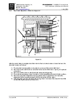
6.12.1 Upper and Lower Travel Safety Limit Switch
These limit switches are supplied as standard equipment when the hoist is sold for use in the NORMAL
position.
The Upper and Lower Travel Limit Switches reset automatically and are wired into the “UP” and “DOWN”
control circuits. The switch housing is recessed into the underside of hoist body as part of the lower
chain guide assembly.
NOTE: The upper and lower travel limit switches and/or the slip clutch are emergency protection
devices and are not to be used as automatic stops during normal hoist operations.
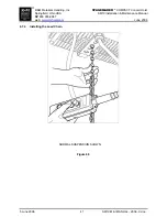
When mounted in the NORMAL position, the hook block activates the upper limit switch as it contacts the
limit switch that is located on bottom side of hoist body. Once switch is activated, the “up” circuit is
opened. The fall stop activates lower limit switch when hook block is lowered to its lowest travel position.
The limit switch is activated and opens the “down” circuit.
The lower limit position is adjustable between the lowest travel and maximum lift. It is adjusted by the
addition of a second fall stop assembly on free end of load chain. A fall stop SHALL always be located at
least 3 feet [91.4 cm] from end of last chain link. The upper limit position is adjustable only when an
additional fall stop assembly is added (1-fall units only) between the hook block assembly and the hoist
body.
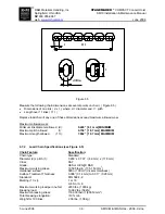
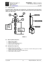
6.12.2 Rotary Geared Limit Switch
The Rotary Geared Limit Switch assembly for the SM10 is mounted inside the body underneath the brake
cover. This feature adds flexibility in adjusting the limits of hoist travel. The mounting of the switch
assembly has an IP55 rating / NEMA 3R type rating.
TWO CONTACTS:
Position 1: Upper limit switch
Position 2: Lower limit switch
FOUR CONTACTS:
Position 1: Lower limit switch
Position 2: Intermediate limit*
Position 3: Intermediate limit*
Position 4: Upper limit switch
(*) Designation of limit switch use may vary with application.
1
4
3
2


