


English
- 51 -
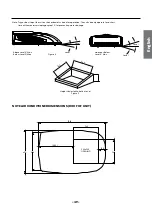
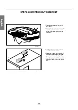
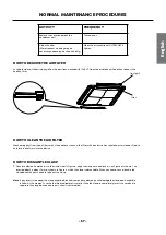
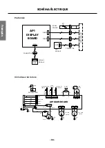
Thickness of vehicle
roof is from 30mm-80mm
Gasket
installtion board
bubble
wind-path
4 bolt
4 bolt
(Max torque is from
2.3Nm~2.5Nm)
Gasket
Outdoor Unit
foam(top)
4 screw
Plate of air vent
fig 5-1
fig 5
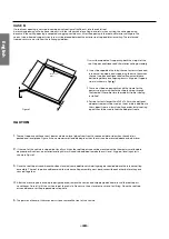
Make sure that you have properly matched the roof top air conditioner and interior ceiling assembly.Caution before
tightening bolts:
1.
Carefully take the ceiling assembly out of the
carton (The remote control packed with the ceiling
assembly).
2.
Remove the ceiling grille from the ceiling assembly.
3.
Before installing the outdoor unit of recreatinal
vehicle air conditioner on the vehicle’s top,
preinstall the plate of air vent and foam (upper) on
the chassis of the outdoor unit with 4pc of screws
(25mm long) (See fig.5-1) .
4.
Then carry the outdoor unit to the vehicle’s top and
align with the openings on the vehicle’s top. Use 2
sets of mounting plate assembly and 4 screw bolts
to mount the outdoor unit (See fig. 5).
5.
You must start (thread) themounting bolts by hand
to avoid cross-threading. DO NOT START THE
MOUNTING BOLTS WITH AN AIR GUN. The mounting
bolts should be tightened, process is completed
when the basepan gasket has been evenly
compressed.
6.
Before installing the air duct assembly of the
indoor unit of recreational vehicle airconditioner,
assemble the foam assembly according to the
thickness of the vehicle’s top. After simulated
installation, use an appropriate amount of sponge
and foam assembly. Stick the sponge and foam
assembly with double faced adhesive tape
(prepared by user) (See fig.5-2, 5-3).
7.
Install the foam assembly on the air duct assembly.
Use 4 screw bolts to fix the air duct assembly onto
the mounting plate. After connecting the outdoor
unit with indoor unit, check whether the foam
assembly has come loose (See fig.5)
1. The applicable thickness of vehicle roof ranges from 30mm~80mm.
2. Before tightening bolts, screw in the four bolts manually and prohibit screwing forcibly.
3. When screwing bolts, you can use automatic tool. Do not tighten one bolt
completely and then tighten other bolts, in order to prevent sticking of screw thread.
4. The max torque for tightening ranges from 2.3Nm~2.5Nm. The following step by step instructions must be
performed in the following sequence to ensure proper installation.
STEP 3-INSTALLING THE CEILING ASSEMBLY


