background image

Section III - Controller

50


Quincy Compressor

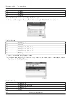
Text on image

(1)

Week Timer

(2)

Week Action Schemes

(3)

Week Cycle

(4)

Status

(5)

Week Timer Inactive

(6)

Remaining Running Time

The first item in this list is highlighted. Select the item to be adapted and press the Enter 

key on the controller to modify.

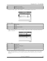
Programming week schemes

• Select Week action schemes and press Enter. A new window opens. The first item 

in the list is highlighted in red. Press the Enter key on the controller to modify Week 

Action Scheme 1.

Text on image

(1)

Week Action Schemes

(2)

Week Action Schemes 1

(3)

Week Action Schemes 2

(4)

Week Action Schemes 3

(5)

Week Action Schemes 4

Содержание QOF 20

Страница 1: ...This manual contains important safety information and should be made available to all personnel who operate and or maintain this product Carefully read this manual before attempting to operate or per...

Страница 2: ......

Страница 3: ...er General 14 Control panel 16 Icons used 17 Main screen 22 Calling up menus 26 Shutdown warning 27 Shutdown 31 Inputs menu 32 Outputs menu 35 Counters 36 Control mode selection 37 Service menu 39 Set...

Страница 4: ...tor 84 Safety valve 84 Belt set exchange and tensioning 85 Cleaning the compressor element 85 Replacement of the outlet pipe 87 Dryer maintenance 88 Section VIII Problem solving 89 Section IX Technica...

Страница 5: ...eath All electrical work must be performed by a qualified electrician CAUTION This symbol identifies hot surfaces which could result in personal injury or property damage IMPORTANT Throughout this man...

Страница 6: ...g Do not depend on check valves to hold system pressure A properly sized pressure relief valve must be installed in the discharge piping ahead upstream of any shutoff valve block valve heat exchanger...

Страница 7: ...d in this manual however possible product updates and changes may have occurred since this printing Quincy Compressor reserves the right to change specifications without incurring any obligation for e...

Страница 8: ...ting at 145 PSIG full load pressure or less Standard Warranty Quincy Compressor Seller warrants products of its own manufacture against defects in workmanship and materials under normal use and servic...

Страница 9: ...An electric cabinet with the electric components is located behind the front panel The compressors can be delivered with or without integrated refrigerant air dryer QOF is the type designation of the...

Страница 10: ...g principle Each compressor element consists of a fixed scroll shaped housing and a scroll shaped rotor Air enters the compressor element through inlet opening 1 Once the air is drawn in the orbiting...

Страница 11: ...4 Orbiting scroll Compressor module The QOF 20 has four 3 7 kW modules while the QOF 22 and the QOF 30 respectively have three or four 5 5 kW modules 3 7 kW compressor module 5 5 kW compressor module...

Страница 12: ...Section II Description 8 Quincy Compressor Flow diagram Flow diagram...

Страница 13: ...s a water separator 111 and flows to the outlet valve 121 On standard compressors with an integrated air dryer the compressed air flows through a common refrigerant dryer 300 before reaching the outle...

Страница 14: ...ontroller performs following functions Monitoring the pressure Protecting the compressor Monitoring components subject to service Automatic restart after voltage failure For more details please consul...

Страница 15: ...e protection The compressor is equipped with an ambient temperature sensor The sensor creates a warning message on the controller if the ambient temperature rises above 40 C 104 F If the ambient tempe...

Страница 16: ...ule 5 5 kW compressor module CAUTION When the compressor is stopped due to overheating the compressor will not restart until the failure is acknowledged and the compressor is restarted manually See al...

Страница 17: ...The refrigerant leaves the capillary tube at evaporating pressure The refrigerant enters evaporator 2 where it withdraws heat from the compressed air by further evaporation at constant pressure The h...

Страница 18: ...ammable settings General Control panel Introduction The controller has following functions Controlling the compressor Protecting the compressor Monitoring components subject to service Automatic resta...

Страница 19: ...a warning will appear on the controller display 1 and the general alarm LED 2 will light up In case of repetitive stops due to a too high temperature a manual reset will be necessary before restarting...

Страница 20: ...Flashes in case of a shutdown is lit in case of a warn ing condition 5 Pictograph Service 6 Service LED Lights up if service is needed 7 Automatic operation LED Indicates that the regulator is automat...

Страница 21: ...s stopped the icon stands still When the compressor is running the icon is rotating Compressor status Motor stopped Motor running Machine control mode Or Local start stop Remote start stop Network con...

Страница 22: ...tion functions Emergency stop Shutdown Warning Service Service required Main screen display Value lines display icon Chart display icon General icons No communication network problem Not valid Input i...

Страница 23: ...cy Compressor 19 Special protection System icons Icon Description Compressor element LP HP Dryer Fan Drain Filter Motor Failure expansion module Network problem General alarm The compressor module is...

Страница 24: ...ompressor The compressor module is stopped and is ready to start The compressor module is awaiting the minimum stop time to expire Menu icons Icon Description Inputs Outputs Alarms Warnings shutdowns...

Страница 25: ...Section III Controller Quincy Compressor 21 Event history saved data Access key User password Network Setpoint Info Navigation arrows Icon Description Up Down...

Страница 26: ...ys is pushed It is switched off automatically after a few minutes when no keys are pushed Typically 6 different main screen views can be chosen 1 Two value lines 2 Four value lines 3 Chart High resolu...

Страница 27: ...ture at one of the compressor element outlets Section B shows Status icons Following icon types are shown in this field Fixed icons These icons are always shown in the main screen and cannot be select...

Страница 28: ...set To reset a timer or message To activate an action button highlight the button by using the Scroll keys and press the Enter key To go back to the previous menu press the Escape key Chart views Inst...

Страница 29: ...he variation of the selected input per day The screen shows the evolution over the last 10 days Selection of a main screen view To change between the different screen layouts select the far right icon...

Страница 30: ...l keys 3 Escape key 2 Enter key Procedure When the voltage is switched on the Main screen is switched on automatically Typical Main screen 2 value lines To go to the Menu screen select action button M...

Страница 31: ...t temperature Too high dew point temperature on compressors with integrated refrigerant dryer High element temperature When a compressor element temperature exceeds the warning level the element stops...

Страница 32: ...blem cause 2 Switch on the voltage and reset the element manually by selecting the warning icon or go to warning menu elements and press Reset Warning element screen element 2 is triggered Text on ima...

Страница 33: ...odify High ambient temperature If the ambient temperature is above the factory setting 40 C 104 F a warning is triggered and a warning icon 1 is shown on the main screen Main screen with high ambient...

Страница 34: ...ted alarm icon will be flashing if the dew poin temperature exceeds the warning level Main screen with dew point exceeding the limit Text on image 1 Compressor outlet pressure 2 Warning icon 3 Load 4...

Страница 35: ...ature is above the factory set shutdown temperature 45 C 113 F the compressor will be stopped and a stop icon will be shown on the main screen of the controller Main screen shutdown by too high ambien...

Страница 36: ...etc To select the digital input to be shown on the chart in the main screen Procedure Starting from the Main screen Move the cursor to the action button Menu and press the Enter key Following screen a...

Страница 37: ...wn below an item in the list means this input signal is shown on the chart at the main screen Any analog input can be selected Selecting another input signal as main chart signal With the Modify butto...

Страница 38: ...troller 34 Quincy Compressor Select Yes to remove or No to quit the current action In a similar way another input signal can be highlighted and selected as Main Chart signal Text on image 1 Set As Mai...

Страница 39: ...the general warning contact etc Procedure Starting from the Main screen Move the cursor to the action button Menu and press the Enter key Following screen appears Text on image 1 Menu 2 Regulation Us...

Страница 40: ...enu icon Counters Function To call up The running hours The loaded hours The number of motor starts The number of hours that the regulator has been powered The number of load cycles Procedure Starting...

Страница 41: ...trol mode selection Function To select the control mode i e whether the compressor is in local control remote control or controlled via a local area network LAN Procedure Starting from the Main screen...

Страница 42: ...There are 3 possibilities Local control 1 Remote control 2 LAN control 3 After selecting the required control mode press the Enter key on the controller to confirm your selection The new control mode...

Страница 43: ...ind out which service plans were carried out in the past To modify the programmed service intervals Procedure Starting from the Main screen Move the cursor to the action button Menu and press the Ente...

Страница 44: ...real time hours counter keeps counting also when the controller is not powered A new algorithm is implemented for a better protection of the compressor elements The running hours will be recalculated...

Страница 45: ...the indicated levels the timers must be reset From the Service menu above select Service plan 3 and press Enter Following screen appears Text on image 1 Service plan 2 Level 3 Running hours 4 Real ti...

Страница 46: ...xt service 2 Level 3 Running hours 4 Actual In the example above the A Service level is programmed at 500 running hours of which 0 hours have passed History The History screen shows a list of all serv...

Страница 47: ...d to select the active pressure band Procedure Starting from the Main screen Move the cursor to the action button Menu and press the Enter key Following screen appears Text on image 1 Menu 2 Regulatio...

Страница 48: ...nter key Following screen appears The first line of the screen is highlighted Use the Scroll keys to highlight the setting to be modified and press the Enter key Following screen appears Text on image...

Страница 49: ...er key Following screen appears Text on image 1 Menu 2 Regulation Using the Scroll keys move the cursor to the Event History icon see above Press the Enter key The list of last shutdown and emergency...

Страница 50: ...ss the Enter key Following screen appears Text on image 1 Menu 2 Regulation Using the Scroll keys move the cursor to the Settings icon see above Press the Enter key Following screen appears This scree...

Страница 51: ...g the language the date the date format etc Text on image 1 General 2 Language In Use 3 Time 4 Date 5 Date Format 6 Modify To modify select the Modify button using the Scroll keys and press the Enter...

Страница 52: ...s Procedure Starting from the Main screen Move the cursor to the action button Menu and press the Enter key Following screen appears Text on image 1 Menu 2 Regulation Using the Scroll keys move the cu...

Страница 53: ...e of the four programmed week schemes can be chosen Notice Important remark You can select different timers on one day up to 8 actions It is however not possible to program2actionsatthesametime Thesol...

Страница 54: ...the item to be adapted and press the Enter key on the controller to modify Programming week schemes Select Week action schemes and press Enter A new window opens The first item in the list is highligh...

Страница 55: ...on image 1 Week Action Scheme 1 2 Monday 3 Tuesday 4 Wednesday 5 Thursday 6 Friday 7 Saturday 8 Sunday A new window opens The Modify action button is selected Press the enter button on the controller...

Страница 56: ...ions 3 Remove 4 Start 5 Stop 6 Pressure Setpoint 1 7 Modify A new window opens The action is now visible in the first day of the week Text on image 1 Monday 2 Start 3 Save 4 Modify To adjust the time...

Страница 57: ...ll keys to modify the values of the hours Use the or Scroll keys to go to the minutes Text on image 1 Monday 2 Time 3 Save 4 Modify Press the Escape key on the controller The action button Modify is s...

Страница 58: ...lect the correct actions Press the Enter key to confirm Text on image 1 Monday 3 Are you sure 4 No 5 Yes 6 Save 7 Modify 7 Modify Press the Escape key to leave this window The action is shown below th...

Страница 59: ...cycle is a sequence of 10 weeks For each week in the cycle one of the four programmed week schemes can be chosen Select Week Cycle from the main Week Timer menu list Text on image 1 Week Timer 2 Week...

Страница 60: ...xample Week Action Scheme 1 Text on image 1 Week Cycle 2 Week 1 3 Week Action Scheme 1 4 Week Action Scheme 2 5 Week Action Scheme 3 6 Modify Check the status of the Week Timer Use the Escape key on t...

Страница 61: ...ek Timer Inactive 4 Week 1 Press the Escape key on the controller to leave this window The status shows that week 1 is active Text on image 1 Week Timer 2 Week Action Schemes 3 Week Cycle 4 Status 5 R...

Страница 62: ...sed when the week timer is set and for certain reasons the compressor must continue working for example 1 hour it can be set in this screen This timer is prior to the Week Timer action Text on image 1...

Страница 63: ...display and LED s are still intact Procedure Starting from the Main screen Move the cursor to the action button Menu and press the Enter key 2 Following screen appears Using the scroll keys move the...

Страница 64: ...e time all LED s are lit User password menu Menu icon Password Function If the password option is activated it is impossible for not authorized persons to modify any setting Procedure Starting from th...

Страница 65: ...erver that allows direct connection to the company network or to a dedicated PC via a local area network LAN This allows to consult certain data and settings via a PC instead of on the display of the...

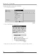
Страница 66: ...Controller 62 Quincy Compressor Configuration of the network card in Windows Go to My Network places 1 Click on View Network connections 1 Select the Local Area connection 1 which is connected to the...

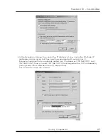
Страница 67: ...select properties 1 Use the check box Internet Protocol TCP IP 1 see picture To avoid conflicts uncheck other properties if they are checked After selecting TCP IP click on the Properties button 2 to...

Страница 68: ...rk connections Configuration of the web server Configure the web interface for Internet Explorer Open Internet Explorer and click on Tools Internet options 2 Click on the Connections tab 1 and then cl...

Страница 69: ...er Multiple IP addresses can be given but they must be separated with semicolons Example Suppose that you already added two IP addresses 192 168 100 1 and 192 168 100 2 Now you add 192 168 100 100 and...

Страница 70: ...ds on the selected options Open your browser and type the IP address of the controller you want to view in your browser in this example http 192 168 100 100 The interface opens Screen shot typical Nav...

Страница 71: ...t will be displayed Only the machine status is fixed and can not be removed from the main screen Analog inputs Lists all current analog input values The measurement units can be changed in the prefere...

Страница 72: ...uts Lists all Digital outputs and their status Special protections Lists all special protections of the compressor Service plan Displays all levels of the service plan and their status This screen sho...

Страница 73: ...Starting pressure 8 bar com pressors psig 58 101 5 116 Starting pressure 10 bar compressors bar e 4 9 10 Starting pressure 10 bar compressors psig 58 130 5 145 Minimum setting Factory setting Maximum...

Страница 74: ...pressors bar e 4 7 8 7 8 Stopping pressure 8 bar compressors psig 58 113 1 113 1 Stopping pressure 10 bar compressors bar e 4 9 8 9 8 Stopping pressure 10 bar compressors psig 58 142 1 142 1 Parameter...

Страница 75: ...on consult your supplier Restart delay This parameter allows to programme that not all compressors are restarted at the same time after a power failure ARAVF active Delay at shut down signal Is the ti...

Страница 76: ...assage Electric cable passage Compressed air outlet Compressed air outlet Manual drain Manual drain Ambient sensor Ambient sensor Automatic drain tube Automatic drain tube Compressor mounting holes Co...

Страница 77: ...ion 2 Ventilation proposals Procedure 1 Install the compressor on a level floor suitable for taking the weight of the compressor in a frost free and preferably low dust location 2 Compressed air outle...

Страница 78: ...calculated from QV 0 92 N t with QV required ventilation capacity in m3 s N nominal motor power of the compressor in kW t temperature increase in the compressor room in C Alternative 2 and 4 The fan c...

Страница 79: ...open to isolate the compressor from the mains before carrying out any connection To preserve the protection degree of the electric cubicle and to protect its components from dust from the environment...

Страница 80: ...nnecting compressor electrically consult Instruction book for motor rotation direction 3 Consult the specific instructions before greasing 4 Manual condensate drain 5 Torques for steel Fe or brass CuZ...

Страница 81: ...e settings of the overload relays See section Electric cable size and fuses 3 Connect the compressor electrically See section Electrical connections 4 Close the condensate drain valve See chapter Cond...

Страница 82: ...art the compressor modules in function of the air pressure 6 On compressors with integrated dryer the nominal pressure dew point will be reached after a few minutes NOTICE The number of starts is limi...

Страница 83: ...op button 2 2 Close the air outlet valve See section Introduction 3 Switch off the voltage 4 Open the manual condensate drain valve Taking out of operation Procedure 1 Stop the compressor and close th...

Страница 84: ...ce schedule especially the service intervals depending on the environmental and operating conditions of the compressor NOTICE The longer interval checks must always include the shorter interval checks...

Страница 85: ...fan ref 124 on Flow diagram fan duct and ele ment cooling fins see note 2 See section Cleaning cooling fins Have orbiting scroll bearing greased see note 3 Every 2 years 5000 B 10 bar and 145 psi comp...

Страница 86: ...ow 15 the tip seals and dust seals need to be replaced more frequently Service kits Service kits For overhauling and for preventive maintenance a wide range of service kits is available Service kits c...

Страница 87: ...5 5 kW compressor module 1 Stop the compressor close the air outlet valve and switch off the voltage 2 Remove the filter cover 1 and the filter element Discard damaged or clogged elements Clean the c...

Страница 88: ...ptimal cooling Safety valve 3 7 kW compressor module 5 5 kW compressor module Operating Operate the safety valve 5 by unscrewing the knurled cap one or two turns Retighten the cap Testing The valve ca...

Страница 89: ...the pulleys Make sure that the pulleys remain aligned The maximum out of line is Maximum parallel out of line 0 5 mm Maximum angular out of line 0 5 degrees 5 Tighten bolts 3 6 Check the belt tension...

Страница 90: ...d depressurise the compressor 3 Remove the fan duct Unscrew the 3 bolts 1 Remove clip 2 if applicable Remove fan duct 3 4 Clean cooling channels Remove dust from the cooling channels 1 by means of air...

Страница 91: ...s List for part number The outlet pipe set contains two parts The plastic insert 3 The metal outlet pipe 1 Procedure 1 Stop the compressor depressurize and switch off the voltage 2 Loosen the coupling...

Страница 92: ...can reach a temperature of up to 110 C 230 F Therefore wait until the dryer has cooled down before removing the side panels Before starting any maintenance or repair work switch off the voltage and c...

Страница 93: ...ings and correct Safety valve opens too soon Replace valve Compressor capacity or pressure below normal Air consumption exceeds capacity of compressor Check equipment connected Choked air inlet filter...

Страница 94: ...Condenser externally clogged Clean condenser Motor of refrigerant compressor stops or does not start The internal thermal protection of the motor has tripped Compressor will restart when the motor wi...

Страница 95: ...s from dust from the environment it is mandatory to use a proper cable gland when connecting the supply cable to the compressor Local regulations remain applicable if they are stricter than the values...

Страница 96: ...100A 90 A 125 A 23 3 A 0 38 A QOF 30 IEC 60 Hz 380 V 53 A 63 A 57 A 63 A 14 5 A 0 26 A QOF 30 IEC 50 Hz 400 V 49 A 63 A 52 A 63 A 13 4 A 0 22 A QOF 30 IEC 50 Hz 400 V N 49 A 63 A 58 A 63 A 13 4 A 0 22...

Страница 97: ...rent carrying capacities in wiring systems The allowed currents are valid for PVC insulated cables with three loaded copper conductors maximum conductor temperature 70 C Installation method B2 accordi...

Страница 98: ...A 160 A 145 A 131 A 112 A 95 mm 223 A 194 A 176 A 158 A 136 A 120 mm 259 A 225 A 205 A 184 A 158 A Installation method F according table B 52 1 Single core cables touching in free air Clearance to wal...

Страница 99: ...ded fuse maximum 63 A In case of single supply cables 3 phases PE configuration 1 I 52 A 10 52 x 1 1 57 2 A The table for installation method B2 allows a maximum current of 54 A for a 16 mm cable For...

Страница 100: ...nstall fuses of half the size of the recommended maximum fuse size on each cable When using 2 x 3 phase 2 PE as in 3 Add 25 to the total current Itot from the tables and divide by 3 Multiply the ampac...

Страница 101: ...4 the maximum current is 25 x 0 88 x 0 8 17 6 A So 2 parallel cables of 3 x AWG12 2 x AWG12 are sufficient Install 20 A fuses on each cable Reference conditions and limitations Reference conditions Ai...

Страница 102: ...dryer psi g 101 5 101 5 101 5 Reference working pressure compressors with integrated dryer bar e 6 75 6 75 6 75 Reference working pressure compressors with integrated dryer psi g 98 98 98 Air tempera...

Страница 103: ...utlet valve compressors without integrated dryer C 32 30 30 Air temperature at outlet valve compressors without integrated dryer F 90 86 86 Air temperature at outlet valve compressors with integrated...

Страница 104: ...otor shaft speed rpm 3505 3505 3505 Nominal motor power kW 4 x 3 7 3 x 5 5 4 x 5 5 Nominal motor power hp 4 x 5 3 x 7 5 4 x 7 5 Sound pressure level compressors without integrated dryer dB A 63 64 65...

Страница 105: ...temperature at outlet valve compressors with integrated dryer C 25 30 55 Air temperature at outlet valve compressors with integrated dryer F 77 86 131 Motor shaft speed rpm 3505 3505 3505 Nominal moto...

Страница 106: ...tandards that have been used for the design are shown and or referred to The Declaration of Conformity Declaration by the Manufacturer is part of the documentation that is supplied with this compresso...

Страница 107: ...han or equal to category II Part number Description Medium Pressure 0830 1009 17 Safety valve Air 9 3 bar 0830 1008 49 Safety valve Air 9 3 bar 0830 1009 18 Safety valve Air 11 5 bar 0830 1008 35 Safe...

Страница 108: ...Declaration of conformity 104 Quincy Compressor Typical example of a Declaration of Conformity document 1 Contact address International Compressor Distribution NV Boomsesteenweg 957 B 2610 Wilrijk Ant...

Страница 109: ...on of Conformity Declaration by the Manufacturer the harmonized and or other standards that have been used for the design are shown and or referred to The Declaration of Conformity Declaration by the...

Страница 110: ...urned to seller freight prepaid for inspection Seller warrants repaired or replaced parts of its own manufacture against defects in materials and workmanship under normal use and service for ninety 90...

Страница 111: ...s risk and storage charges may be applied at the discretion of Seller Accounts past due shall bear interest at the highest rate lawful to contract for but if there is no limit set by law such interes...

Страница 112: ..._________________________________________________________ ____________________________________________________________________ ____________________________________________________________________ ____...

Страница 113: ..._________________________________________________________ ____________________________________________________________________ ____________________________________________________________________ ____...

Страница 114: ...2012 Quincy Compressor All Rights Reserved Litho in U S A Quincy Compressor Products 251 937 5900 E mail info quincycompressor com Website www quincycompressor com...

Отзывы: