


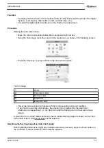


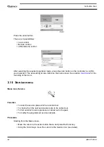


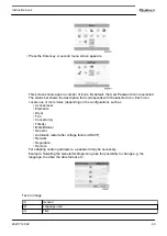


Modifying a service plan
Dependant on the operating conditions, it can be necessary to modify the service intervals. To do
so, use the Scroll keys to select the value to be modified. A screen similar to the one below
appears:
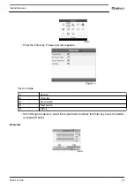
Press the Enter key. Following screen appears:
Modify the value as required using the ↑ or ↓ scroll key and press the Enter key to confirm.
Note:
Running hours can be modified in steps of 100 hours, real time hours can be modified in
steps of 1 hour.
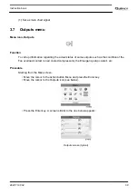
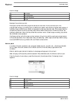
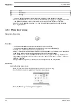
Next Service
Text on image
(1)
Next service
(2)
Level
(3)
Running hours
(4)
Actual
Instruction book
2920 7190 02
45
Содержание QGD 40
Страница 1: ...Quincy Oil injected rotary screw compressors QGD 40 QGD 50 QGD 60 Instruction book...
Страница 2: ......
Страница 14: ...Front view compressors with integrated dryer Instruction book 12 2920 7190 02...
Страница 15: ...Front view open compressors without dryer Instruction book 2920 7190 02 13...
Страница 16: ...Rear view compressors without dryer Instruction book 14 2920 7190 02...
Страница 17: ...Front view open compressors with integrated dryer Instruction book 2920 7190 02 15...
Страница 112: ......
Страница 113: ......
Страница 114: ...No 2920 7190 02 2021 08 Printed in Belgium Performance You Demand Reliability You Trust www quincycompressor com...


