Climate Control Series
Quincy Compressor
2022209100, August 2018
19
If the inlet is routed to outside atmosphere, the inlet piping should be
equipped with a hooded air filter and designed to prevent condensate, water
or snow from being ingested into the compressor.
All inlet piping should be at least the same size (or larger) in di ameter
as the inlet connection to the compressor. For every 10 feet of inlet piping or
every 90° bend, increase the inlet piping diameter by one pipe size. The inlet
piping must be thoroughly clean inside. Remove all weld slag, rust or dirt.
Galvanized pipe with threaded or flanged fittings is preferred.
Never locate the compressor air inlet system where toxic, volatile or cor-
rosive vapors, air temperatures exceeding 100°F, water, or extremely dirty
air could be ingested. These types of at mospheres could adversely affect the
performance of the compres sor system.
•Compressed Air Discharge System
The discharge piping should be of the same diameter as the com pressor
discharge connection, or sized so that the pressure drop at any point in the
system does not exceed 10% of the air receiver pres sure. Install auxiliary air
receivers near heavy loads or at the far end of a long system. This will insure
sufficient pressure if the use is intermittent, or sudden large demands are
placed on the system.
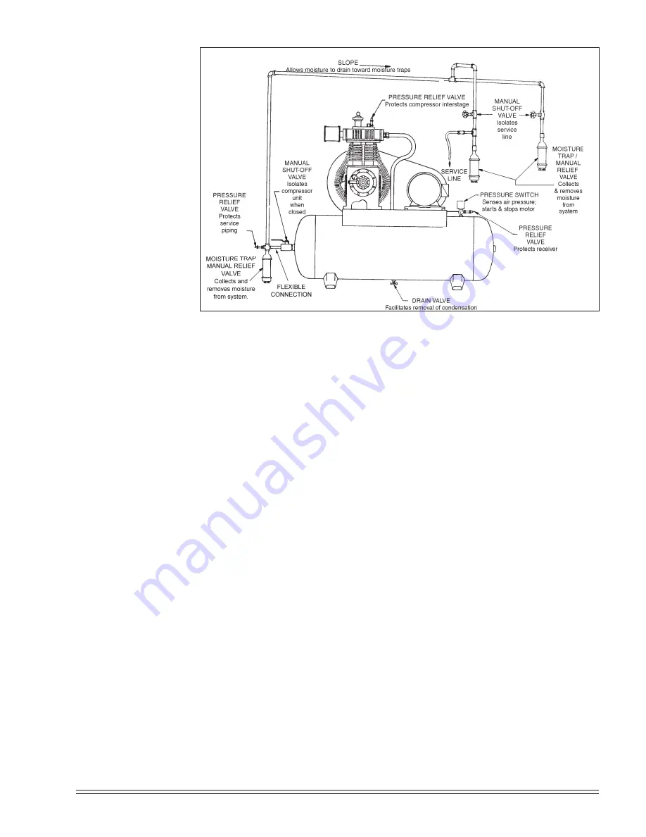
Discharge piping should slope to a drop leg (refer to
Fig. 3-10, Typical
Drop Leg & Component Location
) or moisture trap to pro vide a collection
point where moisture can be easily removed. All service line outlets should be
installed above the moisture traps to prevent moisture from entering the tool
or device using the air. Manual shutoff valves, protected by pressure relief
valves, should be installed at all service line outlets to eliminate leakage while
the tools are not in use.
Fig. 3-10 Typical Drop Leg & Component Location


