QuickWorldWide Big Quick 50 Sport Скачать руководство пользователя страница 30

  Insert the whole construction into the Fuel Tank. Continue tightening but do not 

over tighten or you will ruin rubber stopper! 


Page 30 of 79 

Содержание Big Quick 50 Sport

Страница 1: ...Page 1 of 79 2nd Version...

Страница 2: ...T LIST 13 SECTION 1 UPPER FRAMES 14 SECTION 2 LOWER FRAMES 28 SECTION 3 LANDING GEAR ASSEMBLY 40 SECTION 4 DRIVING SYSTEM 42 SECTION 5 TAIL ASSEMBLY 44 SECTION 6 CONTROL SYSTEMS 50 SECTION 7 ROTOR HEA...

Страница 3: ...be shipped 100 complete and we can assure you that once you fly your helicopter you will love it The QUICK 50 We believe you hold in your hands one of the best helicopters manufactured in the world to...

Страница 4: ...4811 Fax 610 282 4816 Websites http www hhiheli com http www quickheli com http www giantscaleplanes com E mail hhi fast net Office Hours Mon Fri 8 30 6 00 Sat 8 30 1 30 Eastern Daylight Time Technica...

Страница 5: ...stitutes overall design simplicity and represents the future of helicopter technology 7 Heavy Duty Clutch System Based on the same design as our famous heavy duty clutch upgrade that fits most popular...

Страница 6: ...es services to model aircraft pilots As an AMA member you will receive a monthly magazine entitled Model Aviation as well as a liability insurance plan to cover against possible accident or injury All...

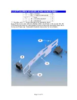
Страница 7: ...Page 7 of 79 REQUIRED TOOLS...

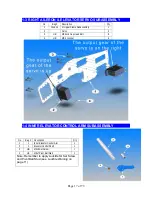
Страница 8: ...HARDWARE OPTIONAL ACCESSORIES GLUES AND THREAD LOCK COMPOUNDS RADIO MOUNTING ACCESSORIES Page 8 of 79...

Страница 9: ...T SYSTEM ENGINES we recommend OS50SX but others may work GLOW PLUGS OS 8 OSMG2691 One Piece Muffler Two Piece Muffler FUEL SYSTEM OTHER HARDWARE OPTIONAL ACCESSORIES 3MM FLYBAR STIFFENERS HHI 402 60 S...

Страница 10: ...G GEAR DAMPENERS HHI2004 Page 10 of 79 SERVO FIXING PLATES Transmits force of fastener to plastic instead of rubber WITH HHI 1205 SERVO MOUNT KIT WITHOUT Includes hardware and fixing plates to mount 5...

Страница 11: ...FINISHING CAPS Adds color and style Distributes force across larger surface area 3mm 4mm 20 pcs in a package 8 pcs in a package BLACK HHIM11100B WITHOUT BLUE HHIM11103 HHIM11108 GOLD HHIM11101 HHIM111...

Страница 12: ...pter they can be the single most important component that contributes to proper function of the helicopter Due to the nature of EMS collective we suggest the use of digital servos to enhance and ensur...

Страница 13: ...rts such as nuts and bolts can be put into containers or trays to prevent losing parts Part No with means that part is not included in the kit The colors of drawings in this manual may look different...

Страница 14: ...ubassembly to make sure there are no missing parts Small parts such as nuts and bolts can be put into containers or trays to prevent losing parts No with means that part is not included in the kit Col...

Страница 15: ...Page 15 of 79...

Страница 16: ...Bolt 8 4 HB M2 5 Locknut 8 Part No with means that part is not included in the kit Note If the servos come with anti vibrating rubber insert them on the servos first We recommend using the servo fixin...

Страница 17: ...4 Cap Head Bolt 8 4 HB M2 5 Locknut 8 1 4 INNER ELEVATOR CONTROL ARM SUBASSEMBLY No Bag Description Qty 1 1 Inner Elevator Control Arm 1 2 1 Elevator Control Shaft 1 3 HB M3x5 Set Screw 1 4 HB M3x7 Pi...

Страница 18: ...JP Weld glue 1 Install Counter Gear to Counter Gear Shaft using Counter Gear Lock Pin No 3 and M4 E clip to secure it Apply JP Weld glue around the pin Put Counter Gear Bearing Block the lower in with...

Страница 19: ...Set Screw 1 5 HB M3x4 Pivot Ball Stud 5 6 HB M3x5x3 Spacer 1 7 1 Right Aileron Control Lever 1 8 HB M3x12 Cap Head Bolt 1 Note The Inner Elevator Control Arm belongs to Inner Elevator Control Arm Sub...

Страница 20: ...6 a Right Upper Frame up to step 1 6 a 1 2 1 Washout Anti Rot Guide 1 3 HB M3x5x3 Spacer 2 4 HB M3x45 Cap Head Bolt 2 Note The Elevator Control Shaft is designed to fit tight in the bearings Sometime...

Страница 21: ...O MODEL No Bag Description Qty 1 Step 1 6 a Right Upper Frame up to step 1 6 a 1 2 1 Washout Anti Rot Guide Base 1 3 Frame Washout Anti Rot Guide A 1 4 HB M3x5x3 Spacer 2 5 HB M3x10 Cap Head Bolt 2 6...

Страница 22: ...escription Qty 1 Step 1 6 c Right Upper Frame up to step 1 6 b 1 2 1 Main Shaft Bearing Block 2 3 HB M3x8 Cap Head Bolt 4 Note For the Upper Bearing Block the flange should face down For the Lower one...

Страница 23: ...m Cross Member 4 4 1 Clutch Bearing Block 1 5 HB M3x8 Cap Head Bolt 12 6 Frame Bulkhead 1 7 1 28mm Cross Member 1 8 1 10mm Spacer 1 9 HB M3x18 Cap Head Bolt 1 10 HB M3x7 Flat Washer 6 Note For the Clu...

Страница 24: ...rame Subassembly 1 9 HB M3x10 Cap Head Bolt 2 3 HB M3x5x3 Spacer 2 10 1 28mm Cross Member 1 4 1 Left Aileron Control Lever 1 11 1 10mm Spacer 1 5 HB M3x4 Pivot Ball Stud 3 12 HB M3x18 Cap Head Bolt 1...

Страница 25: ...il Transmission Subassembly to the frame Note The Elevator Control Shaft is designed to fit tight in the bearings Sometime you might have to sand it a little to get it go into the bearings Note The El...

Страница 26: ...rior with an x acto blade or sand paper Put the Clutch Lining in the Clutch Bell and mark it for cutting the length is around 134mm Cut the Clutch Lining Apply the adhesive thin and even and finish th...

Страница 27: ...Note It is very important to use a Dialing Indicator to check the run out of the Clutch Bell The run out should be no more than 0 004 inch 0 10 mm Page 27 of 79...

Страница 28: ...Bag Description Qty 1 Frame Front Lower Frame 2 2 Frame Radio Tray 1 3 2 Long Canopy Standoff 2 4 2 60mm Cross Member 1 5 HB M3x8 Cap Head Bolt 4 6 HB M3X10 Cap Head Bolt 4 7 HB M3x5x3 Spacer 4 8 2 M3...

Страница 29: ...el Tank 1 There are three 3 lines Aluminum fuel tubing that need to be constructed for the tank assembly Depending on the engine you use you may need only two 2 lines One line is the fuel pick up line...

Страница 30: ...Insert the whole construction into the Fuel Tank Continue tightening but do not over tighten or you will ruin rubber stopper Page 30 of 79...

Страница 31: ...FUEL TANK INSTALLATION No Bag Description Qty 1 Step 2 1 Radio Tray Assembly 1 2 Step 2 2 Fuel Tank Assembly 1 3 2 Half Round Cross Member 1 4 Double Side Tape 1 5 HB M3x8 Cap Head Bolt 2 Page 31 of...

Страница 32: ...2 4 THROTTLE SERVO ASSEMBLY No Bag Description Qty 1 Step 2 3 Fuel Tank Installation 1 2 Servo 1 3 HB M2 5x14 Cap Head Bolt 4 4 HB M2 5 Locknut 4 Page 32 of 79...

Страница 33: ...er Frame Assembly 1 2 Step 2 4 Lower Frame Assembly 1 3 Frame Rear Frame 2 4 Frame Gyro Tray 1 5 2 One piece Cross Member 2 6 2 32mm Cross Member 3 7 HB M3x20 Cap Head Bolt 6 8 HB M3x5x3 Spacer 4 9 HB...

Страница 34: ...ASSEMBLY No Bag Description Qty 1 Loose in box Fan Shroud 1 2 2 M2 5x6 Self Taping Screw 4 3 Frame Frame Angle 2 4 2 60 mm Cross Member 1 5 HB M3x10 Cap Head Bolt 4 6 HB M3x8 Cap Head Bolt 4 7 HB M3 L...

Страница 35: ...escription Qty 1 Engine 1 2 2 Fan Hub 1 3 2 Cooling Fan 1 4 HB M3x6 Cap Head Bolt 6 5 2 Engine Hub Collect 1 6 HB M6 Nord Loc Washer 2 7 M6 Hex Nut 1 8 2 Clutch Shoe 1 9 2 Engine Mount 1 10 HB M3x10 C...

Страница 36: ...Page 36 of 79...

Страница 37: ...it is very important to use a Dialing Indicator to check the run out of the Engine Assembly Most of the vibration problems come from this The run out should be no more than 0 004 inch 0 10 mm Page 37...

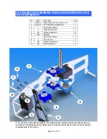
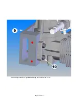
Страница 38: ...Note Engine Mount may look differently from the one in the kit Page 38 of 79...

Страница 39: ...2 8 ENGINE INSTALLATION No Bag Description Qty 1 Step 2 7 Engine Assembly 1 2 Step 2 6 Assembly up to step 2 6 1 3 HB M3x10 Cap Head Bolt 4 4 HB M3 Flat Washer 4 Page 39 of 79...

Страница 40: ...Gear Skids into the Struts Apply CA Glue into the Landing Gear End Cap then insert them into the Skids Drill four 2 5mm holes into the little rounds on the ends of the Struts then secure them with the...

Страница 41: ...Page 41 of 79...

Страница 42: ...ty No Bag Description Qty 1 4 Lower Main Gear 88T 1 4 4 Auto rotation Clutch 1 2 4 Upper Main Gear 97T 1 5 HB M3x6 Cap Head Bolt 4 3 3 Lower Main Gear Hub 1 6 HB M3x6 Philip Screw Flat Head 4 Note The...

Страница 43: ...ly up to step 3 1 6 HB M3 Locknut 1 3 3 Main Shaft 1 7 HB M3X5 Set Screw 4 4 3 Main Shaft Collar 1 Slide the Main Gear Assembly in install the Main Shaft down then secure with one M3x22 Cap Head Bolt...

Страница 44: ...5 5 1 TAIL PULLEY GEAR ASSEMBLY No Bag Description Qty 1 5 Tail Output Shaft 1 2 5 Tail Gear Lock Pin 1 3 5 Tail Pulley Gear 1 4 5 Tail Gear Side Plate 1 5 JP Weld glue 1 Remember apply JP Weld glue a...

Страница 45: ...1 Tail Pulley Gear Assy 1 8 5 Tail Case Cross Member 1 17 HB M2 5x6 Cap Head Bolt 1 9 HB M3x4Pivot Ball Stud 2 18 HB M3x7 Flat Washer 1 First to prevent the Boom End from rotating drill a 2 5mm hole o...

Страница 46: ...Page 46 of 79...

Страница 47: ...ertical Fin Mount A 1 3 5 Tail Blade 2 11 5 Vertical Fin Mount B 1 4 5 Tail Blade Spacer 4 12 5 Horizontal Fin 1 5 HB M2x8 Phillips Screw 2 13 5 Vertical Fin 1 6 HB Shim Ball 2 14 HB M3 Locknut 4 7 HB...

Страница 48: ...this subassembly on the output shaft then secure it with one M3x5 Set Screw Wrap electric tape around the boom couple times where you are going to install the fin mounts Note Fin set may look lightly...

Страница 49: ...urn the Tail assembly so that the Tail Output Shaft pointing upward put the belt onto the Transmission then twist the Tail Assembly 90o to the right Make sure the belt not too tight or loose Tighten t...

Страница 50: ...her 4 4 HB M2X4 Phillips Screws 7 Note There are two kinds of the Swashplate One has little holes maybe 7 4 or 3 of them The other has no hole on it Both work the same If you got the one with holes ju...

Страница 51: ...Ball Stud 2 3 6 Washout Link 2 7 HB M3x12 Cap Head Bolt 2 4 6 Washout Link Pin 2 8 HB M3X5X1 Spacer 2 Note There are some versions of the Washout Base Item No 1 All of them work the same but they shou...

Страница 52: ...tion Qty 1 Sep 6 1 Swashplate Assembly 1 2 Step 6 2 Washout Assembly 1 3 Step 5 Assembly up to step 5 1 4 6 Swash Anti rotation Pin 1 Note the frame may look differently from the one in the kit Connec...

Страница 53: ...ad Bolts 1 or four M3x4 Pivot Ball Stud 2 or two M3x14 Cap Head Bolt Note Some Center Hubs are designed for one O ring each side If this is your case use one O ring each side The beveled edge of the T...

Страница 54: ...ud 2 12 Step 7 1 Main Rotor Hub 1 5 HB M4x6x1 Spacer 4 13 HB M3x7 Flat Washer 2 6 7 Fly Bar Control Arm A 2 14 7 2 3x10mm Linkage Rod 2 7 7 Fly Bar Control Arm B 2 15 7 Washout Anti rotation Pin 2 8 I...

Страница 55: ...1 Step 7 2 Completed Rotor Head step 7 2 1 2 Step 6 3 Helicopter up to step 6 3 1 3 HB M3x20 Cap Head Bolt 1 4 HB M3 Locknut 1 Install the Head Assembly into the Main Shaft and then secure it by one M...

Страница 56: ...8 Rudder Pushrod Guide 3 5 8 Rudder Pushrod Guide Insert 3 6 HB Shim Ball 1 7 HB M2x8 Phillips Screw 1 8 Servo Arm 1 9 M3 Servo Phillips Screw 1 10 8 2 3mm Long Ball End 2 11 CA Glue 1 12 Electric Tap...

Страница 57: ...a little bit bigger than the diameter of the boom Cut off 5 6 teeth of the clamp and wrap the Boom with a couple of wraps of electrical tape to keep it from slipping The length of the Rudder Rod meas...

Страница 58: ...and coded as following No Code Rod Description Center to Center Qty 1 A 2 3x25mm Rod 51 5 mm 2 2 B 2 3x35mm Rod 64 mm 3 3 C 2 3x40mm Rod 66 5 mm 2 4 D 2 3x65mm Rod 94 5 mm 2 5 E 2 3x80mm Rod 110 mm 2...

Страница 59: ...A 51 5 mm 2 8 8 1 Helicopter up to step 7 1 2 B 64 mm 3 9 Double Servo Arm 3 3 C 66 5 mm 2 10 HB Shim Ball 8 4 D 94 5 mm 2 11 HB M2x8 Phillips Screw 8 5 E 110 mm 2 12 M3 Servo Phillips Screw 4 6 F 124...

Страница 60: ...Page 60 of 79...

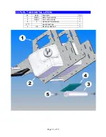
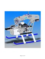
Страница 61: ...Note the frame may look differently from the one in the kit Page 61 of 79...

Страница 62: ...2 Note For some kinds of engines and mufflers you may have to cut the frame angle to make room for screws to fit Although the drawings do not show the valves for hoses you need to put one somewhere be...

Страница 63: ...Page 63 of 79...

Страница 64: ...Page 64 of 79 8 5 MAIN BLADE INSTALLTION No Bag Description Qty 1 Step 8 4 Helicopter up to step 8 4 1 2 Main Blade 2 3 Main Blade Spacer 4 4 8 M4x30 Cap Head Bolt 2 5 8 M4 Locknut 2...

Страница 65: ...hook up Note The frame may look differently from the one in the kit Instead of giving you the exact length of each linkage rod we will explain to you what you are trying to achieve This is the same f...

Страница 66: ...ll line up 100 correct If they are visible off from the 90o position the use the sub trim function in your radio for fine tuning do not use regular trim for this see picture 1 Now you have a good star...

Страница 67: ...at you have free travel in all directions and stick positions When the Pitch stick is all the way up it should look like picture 3 As you can see there is still plenty of room for aileron and elevator...

Страница 68: ...Tail Center Picture 6 Tail Positive Thrust Picture 7 Tail Negative Thrust Picture 8 Tail Pitch Travel Setup Collective Position Normal Flying Aerobatic Up 100 10o 10o Center 50 5o 0o Down 0 3o 10o Pag...

Страница 69: ...Throttle Curve Setup Fuel Electric non governor mode Collective Position Normal Flying Aerobatic Normal Flying Aerobatic Up 100 100 100 85 85 Center 50 70 60 75 75 Down 0 10 100 0 85 Page 69 of 79...

Страница 70: ...are looking for Your goal is to achieve a constant head speed once the helicopter is airborne If you ad pitch climb you need to ad power throttle to compensate for the added resistance a higher blade...

Страница 71: ...t 4 4 HB M3x10 Cap Head Bolt 4 Put the Canopy on the helicopter mark the right positions for 4 holes and then drill four 5 5mm holes Install the Canopy Grommets on the Canopy Secure the Canopy by 4 M3...

Страница 72: ...ing Check the two control paddles for level parallel and proper direction Make sure the batteries are fully charged and the fuel tank is full Make sure the radio and receiver are on and all controls o...

Страница 73: ...perly before flight The main and tail rotors blades operate at very high speed rpm therefore make sure nothing can come into contact with them while they are spinning Perform a range check on the radi...

Страница 74: ...djust one of the pushrods that connect to the main rotor blade pitch arm Out of track Repeat steps a to c until the blades are in track Trimming Most of new built helicopters are unstable But if you t...

Страница 75: ...the tail rotor control stick c Now increase the throttle collective gently to lift the helicopter landing gear off the ground to no more than 4 inches 10 cm At the beginning it is very difficult for...

Страница 76: ...il rotor command will yaw the helicopter nose to the left and a right command will yaw to the right Also a left cyclic command will cause the helicopter to translate left Start practice hovering while...

Страница 77: ...60 inches 1 5 m above the ground Hovering at 60 inches b Once you have been comfortable with all the movements and controls in the previous step start using some tail rotor control to make the helicop...

Страница 78: ...eep the helicopter in a cool and dry place Avoid storage under direct sun light or near heat g Please replace any damaged parts if they are discovered during maintenance WHAT IF THE HELICOPTER CRASHED...

Страница 79: ...NS Specification Quick 50 Blades Quick 580 600 mm Length 1115 mm Height 450 mm Fully Equipped Weight 7 5 lbs 3 40 kg Engine 50 70 Frame Thickness 2 0 2 2 mm Spindle 8 0 mm Main Shaft 10 mm Canopy Fibe...

Отзывы: