24
GB
SBC NRG HIGH POWER - REV001A
OPERATION
SINGLE BATTERY CHARGER
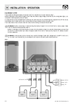
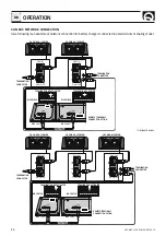
The positive terminal of the battery or of the group of batteries must be connected to one of the positive terminals of
the battery charger. The negative terminal of the battery or of the group of batteries must be connected to the negative
terminal of the battery charger (fig. 1). To make the connections use the cable terminals supplied with the equipment.
If the installation has only one or two groups of batteries, always connect the output marked “MASTER”. This is
the main output of the battery charger. It is advisable to connect the group of batteries which are used more often
(typically the service group) to the MASTER output terminal.
The positive output terminals that are not used must be kept free (do not bridge the terminals).
BATTERY CHARGER IN PARALLEL
(Current sharing mode)
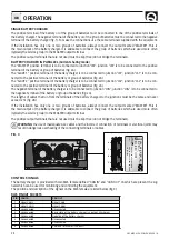
The "MASTER" positive terminal is to be connected to junction "JM"; junction "JM" is to be connected to the positive
terminal of the battery or group of batteries (fig. 2A).
The "SLAVE 1" positive terminal of the battery charger is to be connected to junction "JS1"; junction "JS1" is to be con-
nected to the positive terminal of the battery or group of batteries (fig. 2A).
The "SLAVE 2" positive terminal of the battery charger is to be connected to junction "JS2"; junction "JS2" is to be con-
nected to the positive terminal of the battery or group of batteries (fig. 2A).
The negative terminal of the battery charger is to be connected to junction "JCN"; junction "JCN" is to be connected to
the negative terminal of the battery or group of batteries (fig. 2A).
The lengths of cables that run from the terminals of the battery chargers to the junctions must be the same and never
exceed 2 m (fig. 2B).
If the installation has only one or two groups of batteries, always connect the output marked “MASTER”. This is
the main output of the battery charger. It is advisable to connect the group of batteries which are used more often
(typically the service group) to the MASTER output terminal.
The positive output terminals that are not used must be kept free (do not bridge the terminals).
WARNING:
the use of inadequate size cables and the incorrect connection of terminals or electrical joints may
result in dangerous overheating of the connecting terminals or cables.
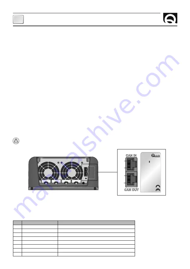
FIG. 3
CAN IN
CAN OUT
CAN IN
CAN OUT
1
8
1
8
OUTPUT
ABSORPTION
XX.XV OL XX.XV SL/GEL/AGM
FLOAT
XX.X OL XX.XV SL/GEL XX.X AGM
XXA MAXIMUM
SBC XXX NRG XX
SN: XXXXXX REV: XXX WY: XX/XX
INPUT XXX-XXX
~
XXXV, XX-XXHz, X.XA MA
X
XXXV, XX-XXHz, X.XA MA
X
CONTROL SIGNALS
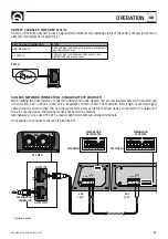
The battery charger is provided with two RJ45 female defined “CAN IN” and “CAN OUT” on which are present the sig-
nals which can be used for monitoring and controlling the equipment.
The position and description of the signals on the RJ45 female are listed below (fig. 3):
RJ45 PINOUT SOCKETS
PIN
CAN IN
CAN OUT
1
Signal CANL
Signal CANL
2
Signal CANH
Signal CANH
3
Unconnected
Unconnected
4
Unconnected
Basic state of the battery charger (+V output, 20mA max)
5
Unconnected
Negative of the battery charger
6
Unconnected
Unconnected
7
Unconnected
Unconnected
8
Unconnected
CAN BUS terminator (124 ohm)
Содержание SBC 1100 NRG FR
Страница 2: ......
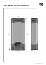
Страница 36: ...36 SBC NRG HIGH POWER REV001A SBC HIGH POWER NRG DIMENSIONI DIMENSIONS mm 220 542 557 243 116 ...
Страница 37: ...NOTES ...
Страница 38: ...SBC NRG HIGH POWER REV001A NOTES ...
Страница 39: ...39 SBC NRG HIGH POWER REV001A ...


