QUICK EA-A10 OPERATION MANUAL
Page 7
7.5
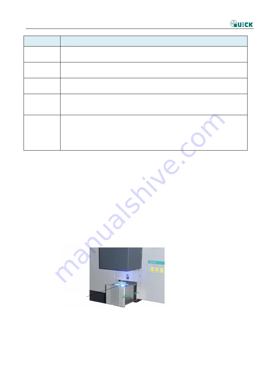
Aligning Arm Instruction
1、
the movement of Aligning arm is control by software ; controlling by
“
aligning in/aligning out
”
in interface of
software.
2
、
arm is used for the element alignment. In the aligning arm. Aligning arm contain camera, camera export video
signal to monitor which produce from PCB and mouth, user can see the picture from monitor, can aligning by
rocker and knob.
3
、
only when top heater reset, Aligning arm can movement.
4
、
when use camera, Aligning arm must be in out, light can adjust by BLUE
、
YELLOW knob, adjust picture by
FOCUS
)
、
(
ZOOM
)
, can obtain clear picture , and micro-adjust, Aligning simpleness .
7.6
Nozzle Instruction
1.
Software can realize auto place and suck chip.
2.
Turn the rocker when optics alignment to make the sucked BGA by the nozzle turning until the stannum
ballpoint in the BGA is superposable with the cuprum point in the PCB. During the process, make the rocker
leftward and rightward, onward and backward for precise alignment.
Key name
Function description
Zoom
Control magnify and reduce of picture, 1~8 zoom ratio in all;
Rotate clo)
,picture magnification, anticlockwise(-)
,reduction
Focus
Camera focus key
Rotate clockwise (+)
,focus magnification,, anticlockwise(-)
, reduction
TOP-LIGHT
Top white light
Rotate clockwise (+)
,blue
white
brighten, anticlockwise (-)
,darken
BOT-LIGHT
Bottom orange light
Rotate clockwise (+)
,
orange
light brighten , anticlockwise (-)
, darken
Z
Rotate clockwise (+)
,downward movement, anticlockwise (-)
,upward movement
Press Z rotate,(prism state is OUT), realize change
“
high speed mode
”
and
“
low speed
mode
”
can see state of soft
Aligning prism


