LTE-A Module Series
UMTS<E EVB R2.0 User Guide
UMTS<E_EVB_R2.0_User_Guide 19 / 44
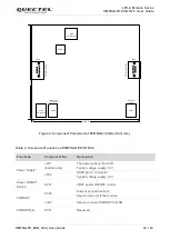
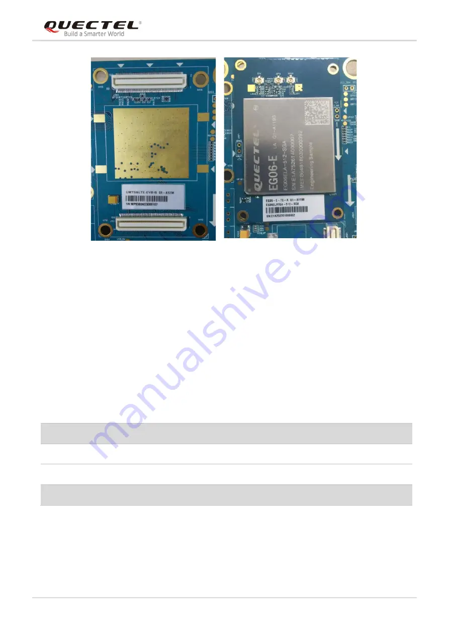
J102
J101
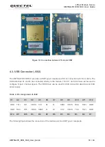
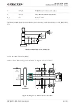
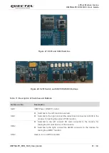
Figure 10: Connection between TE-A and EVB
4.3. USB Connector (J502)
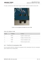
The UMTS<E EVB R2.0 provides a USB Type-C receptacle J502 for connection with the module. The
USB data lines D+ and D- are connected directly to the module. The CC1 and CC2 lines can be used to
configure Type-C channel signals. The VBUS lines can be used for USB connection detection and EVB
power supply.
Table 4: Pin Assignment of J502
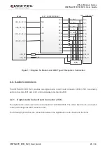
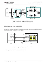
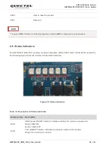
The following figure shows the connection of the module and the USB Type-C receptacle.
A1
A2
A3
A4
A5
A6
A7
A8
A9
A10
A11
A12
GND TX1+
TX1-
VBUS
CC1
D+
D-
SBU1
VBUS
RX2-
RX2+
GND
GND RX1+
RX1-
VBUS
SBU2
D-
D+
CC2
VBUS
TX2-
TX2+
GND
B12
B11
B10
B9
B8
B7
B6
B5
B4
B3
B2
B1

