Smart LTE Module Series
SC66 Hardware Design
SC66_Hardware_Design 58 / 139
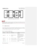
It is important to route the USB signal traces as differential pairs with total grounding. The impedance
of USB differential trace is 90
Ω.
The ground reference plane must be continuous, without any cuts or any holes under the USB
signals, to ensure impedance continuity.
Pay attention to the influence of junction capacitance of ESD protection devices on USB data lines.
Typically, the capacitance value should be less than 2pF for USB 2.0 and less than 0.2pF for USB 3.1
besides. Keep the ESD protection devices as close as possible to the USB connector.
Do not route signal traces under crystals, oscillators, magnetic devices, audio signal, and RF signal
traces. It is important to route the USB differential traces in inner-layer with ground shielding on not
only upper and lower layers but also right and left sides.
USB 3.1 signal line should not be routed under the RF signal line. Crossing and parallel with RF
signal line is forbidden. The signal isolation between USB3.0 signal and RF signal should be
>
90db,
otherwise, the RF signal will be seriously affected.
Make sure the trace length difference between USB 3.1 RX and USB 3.1 TX differential pairs do not
exceed 0.7mm.
Make sure the trace length difference between USB 2.0 DP and USB 2.0 DM differential pairs do not
exceed 2mm.
For USB 3.1, the spacing between Rx and Tx signal traces should be three times the signal trace
width. The spacing between USB 3.1 signal trace and other signal lines should be four times the
signal trace width. For USB 2.0, the spacing between DP and DM signal traces should be three times
the signal trace width and the spacing between USB 2.0 signal trace and other signal lines should be
four times the signal trace width.
For DisplayPort,
the routing length difference between DP_AUX_N and DP_AUX_P should be less
than 7mm.
3.10. UART Interfaces
The module provides the following four UART interfaces:
UART6: 4-wire UART interface, hardware flow control supported.
DEBUG UART: 2-wire UART interface, used for debugging by default.
UART1: 2-wire UART interface.
LPI_ UART _2: 2-wire low power UART interface.
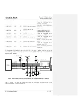
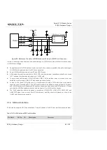
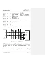
The following table shows the pin definition of UART interfaces.
Table 16: Pin Definition of UART Interfaces
Pin Name
Pin No.
I/O
Description
Comment
DEBUG_TXD
5
DO
DEBUG UART transmit 1.8 power domain.

