GSM/GPRS/GNSS Module Series
MC60 Series Hardware Design
MC60_Series_Hardware_Design Confidential / Released 70 / 114
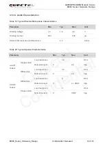
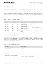
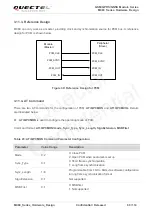
AT+QPCMVOL
is used to configure the input and output volume of PCM.
Command format:
AT+QPCMVOL=vol_pcm_in, vol_pcm_out
Table 24: AT+QPCMVOL Command Parameter Configuration
3.12. (U)SIM Card Interface
The (U)SIM card interface circuitry meets GSM Phase 1 and GSM Phase 2+ specifications, and supports
FAST 64kbps (U)SIM card (intended for use with a (U)SIM application tool-kit).
The (U)SIM card is powered by an internal regulator in the module. Both 1.8V/3.0V (U)SIM cards and
Dual (U)SIM Single Standby function are supported.
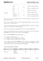
Table 25: Pin Definition of (U)SIM Card Interface
Parameter
Value Range
Description
vol_pcm_in
0~32767
Set the input volume
vol_pcm_out
0~32767
Set the output volume
The voice may be distorted when this value exceeds 16384.
Pin Name
Pin No.
I/O
Description
Alternate
Function
1)
SIM1_VDD
18
PO
Supply power for (U)SIM1 card.
Automatic detection of (U)SIM1 card voltage.
Voltage accuracy: 3.0V±5% and 1.8V±5%.
Maximum supply current is around 10mA.
SIM1_CLK
19
DO
Clock signal of (U)SIM1 card
SIM1_DATA
21
IO
Data signal of (U)SIM1 card
SIM1_RST
20
DO
Reset signal of (U)SIM1 card
SIM1_PRESENCE
37
DI
(U)SIM1 card insertion detection
DTR
SIM_GND
16
Specified ground for (U)SIM card
SIM2_VDD
13
PO
Supply power for (U)SIM2 card.
Automatic detection of (U)SIM2 card voltage.
Voltage accuracy: 3.0V±5% and 1.8V±5%.
Quectel
Confidential

