background image

GV50

TRAC

2.3.

The 

L-lin

follo


Tabl

Inde

10 

11 

12 

00


User


Manua

CGV500UM001

. Interface

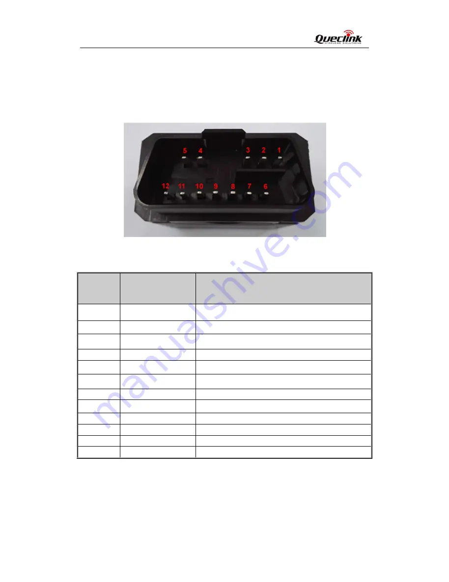
GV500 has a

ne and J185

owing figure:

le 4: Descript

ex 

De

PW

L_

HS

M

J1

K_

HS

GN

GN

M

J1

SW

al


1


e Definitio

an OBD II co

0 bus. The 


Figure 2

tion of OBD I

escription 

WR 

_line 

S_CAN_L 

S_CAN_L 

850_BUS- 

_Line 

S_CAN_H 

ND 

ND 

S_CAN_H 


W_CAN 


onnector. It co

sequence an

2. The 

O

II Connection

C

Ex

H

M

J1

K

H

Po

Po

M

J1

SW


ontains powe

nd definition 

OBD II conn

ns 

Comment 

xternal DC p

line of ISO 9

HS_CAN_H li

MS_CAN_L li

1850 Bus neg

K line of ISO 9

HS_CAN_H li

ower and dig

ower and dig

MS_CAN_H l

1850 Bus pos

W_CAN of I


er supply and 

of the OBD

ector on th

ower input, 8

9141, ISO 914

ine of ISO 11

ine of ISO 11

gative line of 

9141, ISO 91

ine of ISO 11

ital ground

ital ground

line of ISO 11

sitive line of J

SO 11898 an


interfaces of

D II connect

e GV500 

8-32V 

41-2 and ISO

898,J1939 an

898 and ISO

J1850 PWM 

41-2 and ISO

898,J1939 an

1898 and ISO

J1850 PWM a

nd ISO 15765

f CAN bus, K

tor are show


O 14230 

nd ISO 15765

O 15765    

and J1850 V

O 14230 

nd ISO 15765

O 15765    

and J1850 VP


‐ 

8

 ‐   


K-line, 

wn in 

VPW 

PW 

All manuals and user guides at all-guides.com

Содержание GV500

Страница 1: ...V50 TRAC 00 User Manua CGV500UM001 GSM al 1 M GP PRS G Use TRAC V GPS T r Man CGV500U Version 1 0 Tracke nual UM001 02 er GV5 500 0 All manuals and user guides at all guides com a l l g u i d e s c o...

Страница 2: ...ary tech ument and gi en without ex in the event o upplied herein clink Wirele er manual 5 500UM001 service to it esigned by Q d to Queclin ditional relev Furthermore ystem remain ations supplie hnica...

Страница 3: ...tting Started 3 1 Opening 3 2 Closing 3 3 Installin 3 4 Installin 3 5 Device S OBD II related 4 1 Commu 4 2 OBD II P al 1 ry nce and Abbreviat view tion st ce Definition d g the Case the Case ng a SIM...

Страница 4: ...LE 2 TERMS A LE 3 PART LIS LE 4 DESCRIP LE 5 DEFINITI LE 6 COMMU al 1 PROTOCOL RE AND ABBREVIA ST TION OF OBD ON OF DEVIC UNICATION PR T FERENCE ATIONS D II CONNECTIO E STATUS AN ROTOCOLS LIST Table I...

Страница 5: ...2 THE OB URE 3 OPENIN URE 4 CLOSIN URE 5 SIM CA URE 6 BACKU URE 7 GV500 al 1 RANCE OF GV BD II CONNECT NG THE CASE NG THE CASE ARD INSTALLAT P BATTERY IN LED ON THE C 500 TOR ON THE G TION STALLATION...

Страница 6: ...014 03 19 C 015 09 15 A Author Leo LEI Cid Xu Abside Yu Descript Initial Updated Updated Updated Update D Update L ion of chang Introduction the pictures 4 2 OBD II P Document tem LED status an ge in...

Страница 7: ...over GP to first fix lowing the ckend server nd extended stem integrat Track pro y geo fence many other us erence erface Protoc viations ions on ower Supply Diagnostics Automotive E d CAN peed CAN e...

Страница 8: ...E_ al 1 Overview ion on the OBD I ontains an OB ernal GSM an F st t _M Optional II interface G BD II connec ntenna an int Figure 1 l GPS vehicle tr ctor which co ternal GPS an Appearan Pict racking de...

Страница 9: ...l DC p line of ISO 9 HS_CAN_H li MS_CAN_L li 1850 Bus neg K line of ISO 9 HS_CAN_H li ower and dig ower and dig MS_CAN_H l 1850 Bus pos W_CAN of I er supply and of the OBD ector on th ower input 8 914...

Страница 10: ...User Manu CGV500UM0 Getting St Opening rt the triangu case unsnapp ual 001 tarted g the Case ular pry open ed er into the ga ap of the case e as shown below push th 0 he opener up until All manuals an...

Страница 11: ...GV5 TRAC 500 User Manu CGV500UM0 ual 001 Figure 3 Opening g the Case 1 All manuals and user guides at all guides com a l l g u i d e s c o m...

Страница 12: ...battery is glu gged in The s ual 001 the Case ued to top co step of closin over so befor g case is show Clo re closing the wn as followi osing the Ca e case you sh ing ase hould let the 2 battery con...

Страница 13: ...e F g the Inter Fig nal backup Li ard e unit is not holder as sh cut mark Clo Figure 4 rnal Backu ure 5 B i ion battery powered Sli hown below ose the SIM c SIM Card up Battery ackup Batt ide the hold...

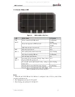
Страница 14: ...s arching GSM registered to G eds pin code powered off no data or data searching GP as gotten GPS power and in GV500 is pow l power and V wer in and int wer in and int GV500 LED ion of Device ED can b...

Страница 15: ...s per minute o ed olant Tempera mption atistics n Indicator La Trouble Code sition d Input atures rotocols BD II system v otocols The l col PWM VPW 141 2 4230 4230 5765 5765 5765 5765 _USER1 _USER2 P2...

Страница 16: ...m istics GV500 and distance ntifier of Veh cause the Veh 0 could get th accumulated hicle Please n hicle manufac he distance in d since DTCs note that not a cturers are re two cases d were cleared all...

Страница 17: ...limits are designed to provide reasonable protection against harmful interference in a residential installation This product generates uses and can radiate radio frequency energy and if not installed...

Отзывы: