background image

8

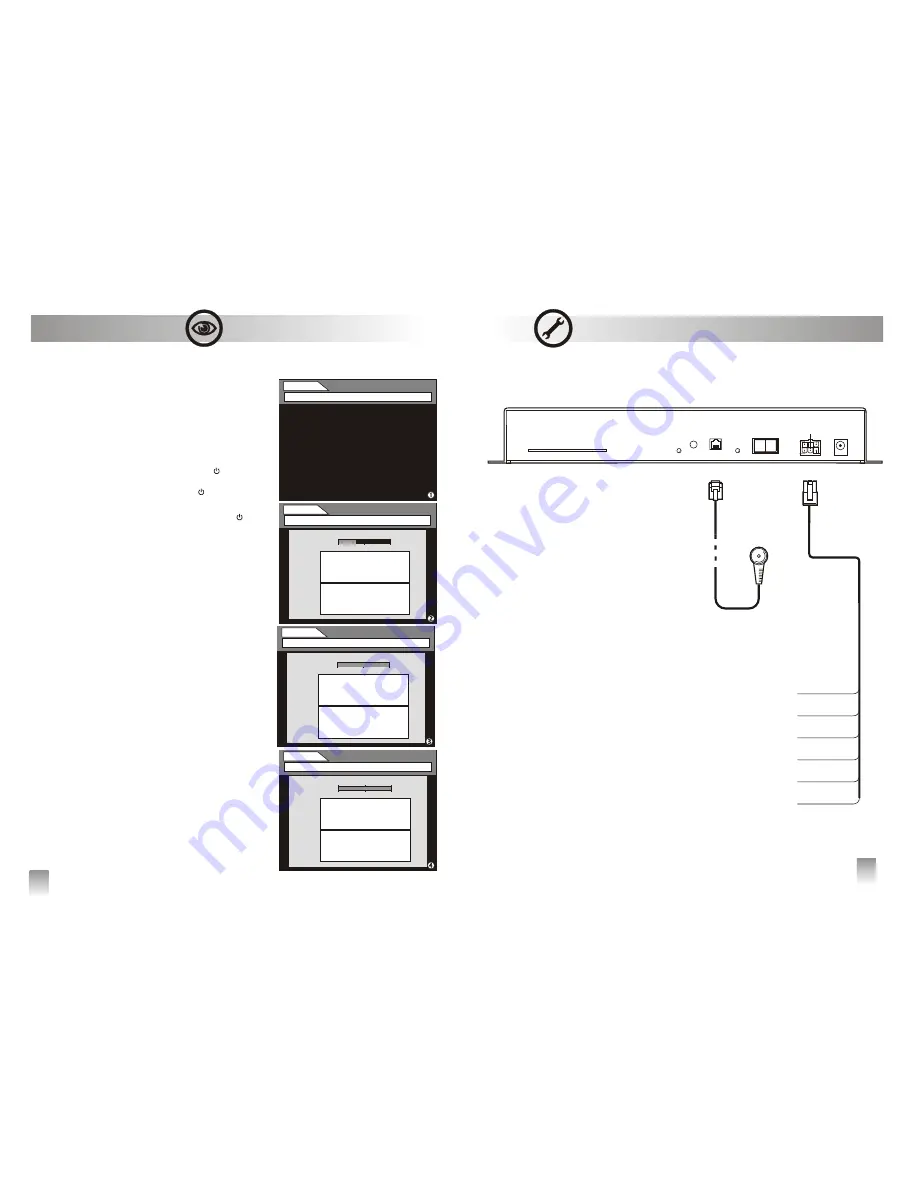
Be sure that every connection has been correctly set, as 
shown on the diagram at page 22.

Turn the unit on, taking on the ON position the switch on 
the front panel, if located

on the front panel is green, 

 is red:


the receiver is on stand-by, press the

 button on

he remote control


on the front panel is green, led

 is 

switched off: 

      after a few seconds frame  will be shown on the screen 

to start the 

It's possible to stop the 

 by pressing EXIT but-

ton. Frame  will be shown on the screen. Press 


button to confirm the scan stop or the

  button 

to resume it.

press 

 button to store the channels in the TV 

LIST. The first channel in the up-to-date TV LIST 
will be shown on the screen.

If at the end of the 

 frame  will be shown 

on the screen, check the connections and the 
installation parameters of the receiver, then press 
in sequence

buttons to re-

launch the scanning.

The two led on the front panel are both switched off:

           Check the connections and begin the getting started 

operations again.


v

 Getting started


  • POWER LED 

 led (  )

 [  ]


t

  • POWER LED

 (  )



      › press [OK] button 

channels tuning pro-

cess. 


tuning

[OK]

 [EXIT]

        At the end of the tuning frame

ƒ

 will be shown on the 

screen.

          ›

[OK]


tuning

[EXIT], [SCAN] e [OK] 

   •  


First Use

21

1

4

6

3

 GND



KEY

(white) -

 Ignition lead 

 Connect to an accessory terminal in the fuse 
block  controlled  by  the  car  ignition  key 
(+12V=ON)

GROUND

(black) - 

Power lead (-)


 Connect to the battery negative pole (car

     chassis)

ƒ

BRAKE

  (blue)  - 

Parking  brake  control 

lead 

   Connect to parking brake or chassis of the car 

(output video engaged)

+12/24V 

(red) - 

Power lead (+)

Connect to a live terminal in the fuse block 
connecting to the car battery 

GROUND 

(black)  - 

Power lead (-)

Connect  to  the  battery  negative  pole  (car 
chassis)

AUX  +12V 

(grey)  - 

Power  output  lead 

for accessory parts

Connect  to  the  device  to  feed (12V/30  mA 
max).  The  device  is  supplied  with  power 
when it is switched on.

FRONT PANEL

Ricevitore infrarosso



 • KEY- White

 • MASSA Black

ƒ

 • BRAKE - Blue

 • IN +12/24V - Red

 • MASSA - Black

 • AUX +12V - Grey

Installation and Connections

TUNING

[OK] to start search - [EXIT] to quit

TUNING

No services found - [EXIT] to quit

0%

TV

0

RADIO

0

50%

100%

TUNING

[OK] to stop - [EXIT] to continue

0%

TV

12

TV

TV

TV

TV

RADIO

RADIO

RADIO

2

50%

100%

TUNING

[OK] to save - [EXIT] to quit 

0%

TV

44

TV 1

TV 2

TV 3

TV 4

RADIO 1

RADIO 2

RADIO 3

RADIO 4

RADIO

3

50%

100%

All manuals and user guides at all-guides.com

Содержание QTM100

Страница 1: ...QTM100 User manual Manufactured and distribuited by Quantum s p a Via Piero e Alberto Pirelli 6 20126 MILANO www qtm it info qtm it All manuals and user guides at all guides com a l l g u i d e s c o m ...

Страница 2: ...on conformity with all the precautions furnished with the instructions manual In the event you require service during the warranty period you should fill in and show the present cer tificate together with a valid receipt issued by the dealer showing the date of purchase of the prod uct WARRANTY VOUCHER Model N matriculation Defect found Purchaser firm Date _ _ _ _ _ _ To return correctly filled in...

Страница 3: ...do so may result in fire or electric shock H A L T U S E I F A P R O B L E M APPEARS D O N O T O P E R A T E A N Y Failure to do so may cause personal FUNCTION THAT TAKES YOUR injury or damage to the product ATTENTION AWAY FROM SAFELY DO NOT USE OLD BATTERIES DRIVING YOUR VEHICLE When inserting batteries in the Any function that requires your remote control be sure to observe prolonged attention s...

Страница 4: ... CD 3 video output for three separated monitor 1 audio stereo output Audio video digital quality Easy and fast plug and play installation DVB T Network Interface Module DVB T COFDM Dual RF Diversity with Anti Doppler Enhancement DVB MPEG2 Transport and De Multiplexing ISO IEC 13818 1 MPEG 2 Transport Stream Compliance Nordig II and ETS 300 744 DVB T Full Compliance Full 47 860 MHz Frequency Range ...

Страница 5: ...option 0 9 alpha numerical button BACK to return to the previous page where available MUTE to switch on off the audio input RED BLUE GREEN to navigate the interactive applications DOWN BUTTON navigation button LEFT BUTTON navigation or volume adjuster button POWER To switch on off the unit A V to select audio video inputs 24 v TECHNICAL FEATURES Operation frequencies 174 230 band III 470 862 bands...

Страница 6: ...e the system s functioning WARNING do not provide external power in case of use of different brand antennas not to occur in doing so may result in product damages and in decay of warranty s terms Be sure to position the two antennas as far away and opposing from each other as possible For example place the first antenna on the right side of the wind screen of the vehicle and the second one on the ...

Страница 7: ...utput to connect to a rear monitor s use the fitting Quantum antennas video input Signal view is not bound teherefore it is always available RCA AUDIO OUTPUT Mono AUDIO VIDEO INPUT A V IN 2 Audio Video inputs to connect an auxiliary unit in for ex The input activation can be selected by remote control AUDIO VIDEO INPUT A V IN 1 Audio Video inputs to connect an auxiliary unit for ex Dvd player rear...

Страница 8: ...els tuning pro cess tuning OK EXIT At the end of the tuning frameƒ will be shown on the screen OK tuning EXIT SCAN e OK First Use 21 1 4 6 3 GND KEY white Ignition lead Connect to an accessory terminal in the fuse block controlled by the car ignition key 12V ON GROUND black Power lead Connect to the battery negative pole car chassis ƒBRAKE blue Parking brake control lead Connect to parking brake o...

Страница 9: ...d acces sory parts Use of other than designed DO NOT SPLICE INTO ELECTRICAL accessory parts may damage this unit or CABLES cause an incorrect functioning of the Never cut away cable insulation to supply appliance power to other equipment Doing so will exceed the current carrying capacity of ARRANGE THE WIRING CORRECTLY the wire and result in fire or electric shock Route the electrical and audio vi...

Страница 10: ...hing 1 A V IN and OUT SWITCHING Imagine figure to connect one device videogame console in A V IN1 input and a second one dvd player in A V In2 input The decoder can be set in three different modes that lead to the following configurations QTM100 on STAND BY FRONT Monitor signal from AV IN2 REARMonitors No signal QTM 100 on TV FRONT Monitorƒ TV signal tuned by QTM 100 REAR Monitors TV signal tuned ...

Страница 11: ... using the up down 5 6 buttons FAVOURITE TV 1 Channel TV 2 Channel TV 3 Channel TV 4 Channel TV 5 Channel TV 6 Channel TV 7 Channel TV TV LIST GREEN to change list 18 Audio Video Switching v Audio video Inputs Ithe receiver allows the user to connect two auxiliary devices for ex Videogame console Dvd player etc Into the audio video input AV In1 e In2 and to select them by the remote control 1 How ...

Страница 12: ... remote control Press MENU SCAN A V OK P P V CHANNEL EXIT info MENU ƒ LIST 17 v DIAGNOSTICS The receiver has two different levels of diagnostics SIGNAL LEVEL RECEIVER DATA s How to view the DIAGNOSTICS press MENU select DIAGNOSTICS by using 3 4 buttons press OK ƒ to confirm the selection or EXIT to can cel it SCAN A V OK P P V CHANNEL EXIT info MENU ƒ LIST Menu DIAGNOSTICS SETTINGS Receiver settin...

Страница 13: ... LIST Menu SETTINGS 13 SETTINGS OK to confirm EXIT to quit DIAGNOSTICS TV LIST PAY TV RECEIVER RESTORE CLOCK TV out 4 3 pan scan Timer sleep 03h Menu language ita SCAN A V OK P P V CHANNEL EXIT info MENU ƒ LIST Menu PAY TV SETTINGS Receiver settings OK to confirm EXIT to quit DIAGNOSTICS TV LIST PAY TV v SETTINGS In this sub menu you can see the parameters related to RECEIVER RESTORE CLOCK WARNING...

Страница 14: ... be shown next to the selected channel If you want to cancel the selection press OK again and the tick signal ü will be deleted 2 How to delete a channel from the Favourite Tv List Follow the same procedure as shown at the point 1 and replace CREATE with DEL CHAN 3 How to sort the Favourite Tv List press MENU select TV LIST and press OK to confirm select SORT LIST and press OK to confirm browse th...

Отзывы: