Manual for WinneX 3E
chapter 2
Note:
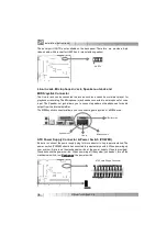
If you chang e “ So ft-o ff by PWR- BTTN” fro m de fault “ Ins tant -off” to “ Delay 4
Secs” in the “ POWER MANA GEMENT SET UP” sectio n of the BIOS, the pow er
sw it ch should be pre ssed for m ore th an 4 se conds be fore the system pow -
ers d ow n.
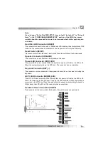
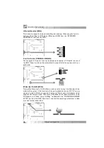
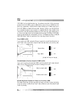
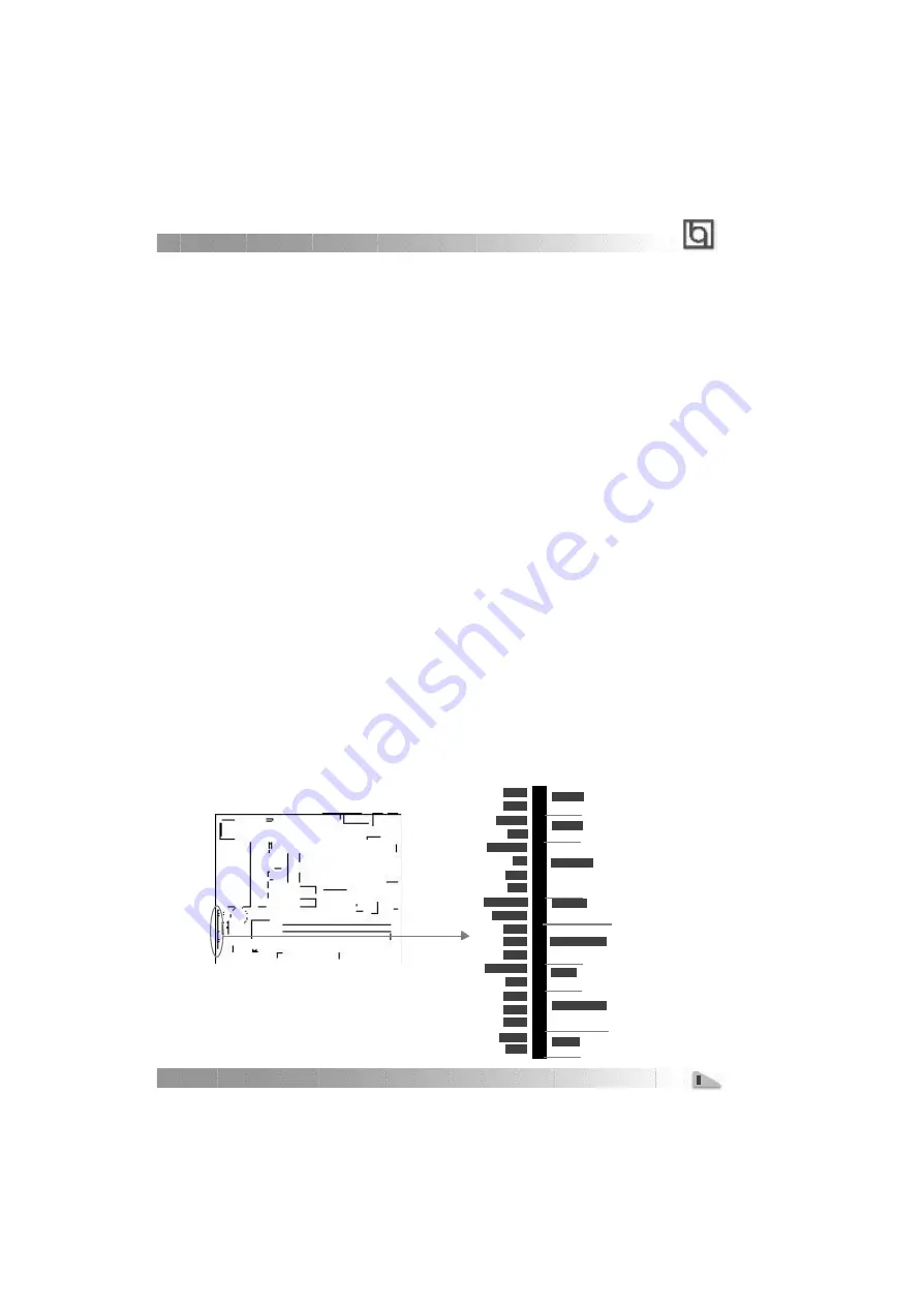
Hard Disk LED Connector (HDLED)
The connector connects to the case’s IDE indicator LED indicating the activity status of IDE
hard disk. The connector has an orientation. If one w ay doesn’t w ork, try the other w ay.
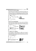
Reset Switch (RESET)
The connector connects to the case’s reset sw itch. Press the sw itch once, the system resets.
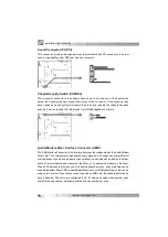
Speaker Connector (SPEAKER)
The connector can be connected to the speaker on the case.
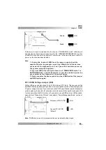
Power LED Connector (PWR_LED)
The pow er LED has tw o status. When the system is in pow er-off status, the LED is off.
When the system is pow ered up, the LED is on. The connector has an orientation.
Key-Lock Connector (KEY_L)
The connector c an be connected to the keyboard lock sw itch on the case for locking the
keyboard.
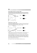
ACPI LED Connector (GREEN_LED)
The A CPI LED has four status. When the system is in pow er-off s tatus, the LED is off.
When first time plug in the 220V pow er supply, the LED is dimmis h. When the system is
pow ered up, the LED is on. When the system enters suspend mode(including Suspend to
RAM status), the LED w ill flash. The connector has an orientation.
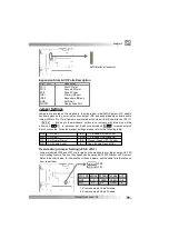
Hardware Green Connector (SLEEP)
Push once the sw itch connected to this header, the system enters suspend mode.


