Manual for WinneX 3E
Expansion Slots & I/O Ports Description
Slot / Port
Description
PCI 1
First PCI slot
PCI 2
Second PCI slot
PCI3
Third PCI slot
IDE 1
Primary IDE port
IDE 2
Secondary IDE port
AMR
AMR slot
FLOPPY
Floppy Drive Port
Jumper Settings
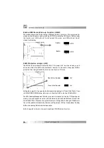
Jumpers are located on the mainboard, they represent, clear CMOS jumper JCC, enable
keyboard passw ord pow er- on function jumper JKB, and enable/disable onboard audio
jumper JSD etc. Pin 1 for all jumpers are located on the side w ith a thick w hite line ( Pin1
→
), referring to the mainboar d’s silkscreen. Jumpers w ith three pins w ill be
show n as to represent pin1 & pin2 connected and to represent pin2
& pin3 connected. For default jumper settings, please refer to the follow ing table:
JFS0
1-2 ( Auto)
JKB
1-2 (Enable KB Pow er -on)
JFS1
1-2 ( Auto)
JUSB
1-2 (Enable USB Wake-Up)
JCC
2-3 ( Normal Status)
JSB
Closed (Connec t PCI 3.3Vsb)
JSD
2-3 ( Enable A udio)
JAV
Open (Enable Flash BIOS)
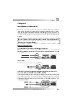
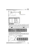
Overclocking Jumper Setting (JFS0, JFS1)
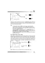
Jumpers labeled JFS0 and JFS1 ar e located on the mainboard providing users w ith CPU
overclocking feature. The host bus speed c an be set as 66/100/133MHz or AUTO select.
Refer to the chart below for the location of these jumpers, and the table for information on
how to s et them.
chapter 2
AMR Interface Connector
JFS1
JFS0
CPU FSB 66MHz 100MHz 133MHz AUTO
JFS1 2-3 2-3 OPEN 1-2
JFS0 2-3 OPEN OPEN 1-2
‘1-2’ represents pin1 & pin2 closed.
‘2-3’ represents pin2 & pin3 closed.


