background image

18

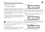
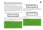
Graphic load percentage indicator shows the fraction of the maxi-

mum possible power at the current input voltage.
The inscription "in" indicates the input voltage in the second line.
The  inscription  "out"  indicates  the  output  voltage  in  the  second 

line.
From left to right: input voltage, in Volts; the percentage of load 

from the maximum possible power at the current input voltage; 

output voltage in Volts and tenths of a Volt

•  ADDITIONAL SCREEN NO.3
 

Displayed after triple-pressing the “Right” button.
From left to right: input voltage, in Volts; the percentage of load 

from the maximum possible power at the current input voltage; 

output voltage in Volts and tenths of a Volt.

Second level menu screens:

The second level menu screens are intended for the advanced 

user.  In  addition  to  monitoring  the  parameters,  some  of  the 

screens enable to change the operation of the device, be careful! 

You can change the output voltage: precise regulation within ±3% 

and switching from 220V to 230V and back. It is also possible to 

test coolers (set the speed to check the quality of the coolers, the 

absence of unnecessary noise). To enter the second level menu, 

long press the left button under the screen (not less than 6s). To 

exit these menu items to the default screens either turn off the 

power or long press the left button again.

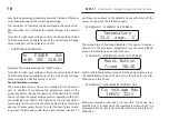
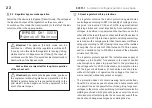
•  SCREEN NO.1. TEMPERATURE SCREEN

The temperature of the main elements of the device, in degrees 
Celsius (°С). The maximum temperature may not exceed 80 de-
grees, otherwise the device will shut down.
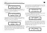
•  SCREEN NO.2. MAXIMUM VALUES INFO SCREEN

Hint for the following three screens. On the peak screens, press 

the middle button to reset it. There are no functions for the mid-

dle button on this screen.

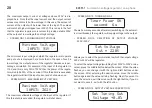
•  SCREEN NO.3. MAXIMUM RECORDED LOAD

Maximum  recorded  load  since  the  last  time  the  device  was 

switched on. It is reset when the regulator is switched off. It is 

displayed in Watts (W). It can also be reset by pressing the mid-

dle button.

In   POWER   Out

160V


25C 


220.2V

Temperature

31.2  degr.  C

Reset Button

fixed  VALVE

Fix Voltage Max

INPUT: 321V

QUANT-7  

 Automatic voltage regulator, one-phase


Содержание QUANT-7

Страница 1: ...QUANT 7 Made in Ukraine 27 1 22049061 001 2021 OUR MERIT SAFE VOLTAGE Automatic voltage regulator one phase Operation manual...

Страница 2: ...ect outlet in the house or in the perfect regulator Therefore in fact the development of QUANT regulators made anew from circuitry algorithms and software list of equipment to design and construction...

Страница 3: ...3 QUANT 7 Automatic voltage regulator one phase Find out all about QUANT stabilizers on the channel https www youtube com channel UCWVXbv4Spwr5yUb U9fvMWw OPERATION MANUAL...

Страница 4: ...ations 8 3 1 Extended specification and technical specifications 9 4 Scope of delivery 10 5 Device and principle of operation 10 6 Installation and connection 13 7 Regulator operation 16 8 Regulator o...

Страница 5: ...5 5 QUANT 7 Automatic voltage regulator one phase...

Страница 6: ...ined space box cabinet i e in conditions of insuffi cient ventilation Do not operate the regulator in direct sunlight or in atmospheric precipitation 1 3 General safety precautions keep children away...

Страница 7: ...or before the overvoltage pulse reaches the load Most dangerous situations are solved without switching off the regulator so that the load receives a clean filtered voltage for phase 220V 230V 50Hz an...

Страница 8: ...erating frequency range Hz 45 50 Operating temperature range 5 40 Humidity range 0 80 Delay before switching on sec 6 Mounting method Hinged Protection index 20 Cooling Forced Low noise Number of phas...

Страница 9: ...tage regulator limits the input and output current taking into account double overload If the value is ex ceeded by 200 of the nominal power the regulator will turn off in 1 second Thanks to the limit...

Страница 10: ...ing from the grid The input voltage from the grid is fed through the input circuit breaker to the input of the regulator circuit initially supplies a low power auxiliary power supply and the motherboa...

Страница 11: ...or its input and output filters reactive pow er compensator for normal operation mode which includes any surges and spikes in voltage within the acceptable regu lation range of the device overvoltage...

Страница 12: ...12 REGULATOR CIRCUIT QUANT 7 Automatic voltage regulator one phase...

Страница 13: ...fixed It is desirable to use special equipment or check the site plan check the site plan If you are not sure if there are any power lines in this If you are not sure if there are any power lines in...

Страница 14: ...on the back panel fit into the slots of the suspension bracket Check the accuracy of the fitting by trying to move each regulator slightly holding back from a possible fall left right and pulling dow...

Страница 15: ...15 15 VOLTAGE REGULATOR INSTALLATION CHART N L Electricity meter 220V socket Stabilizer Automaton QUANT 7 Automatic voltage regulator one phase...

Страница 16: ...ansformers in the presence of both smooth and sudden mains voltage spikes at the regulator input as long as they are within the allowable regulation range the output voltage of the regulator remains u...

Страница 17: ...vailable as soon as the device is turned on They are switched with the Left and Right buttons below the screen left and right buttons Information screens without settings MAIN SCREEN It is displayed b...

Страница 18: ...hin 3 and switching from 220V to 230V and back It is also possible to test coolers set the speed to check the quality of the coolers the absence of unnecessary noise To enter the second level menu lon...

Страница 19: ...RPMs To exit the menu press the middle button again You can safely move further on the menu the device will return the cooling sys tem to normal mode The value is not saved SCREEN NO 7 TECHNICAL SECT...

Страница 20: ...on SCREEN NO 11 MAXIMUM INPUT VOLTAGE The maximum allowable voltage at the input of the regulator If this threshold is exceeded the regulator will shut down SCREEN NO 12 TURN ON DELAY Shows how many s...

Страница 21: ...Changing this parameter may cause the regulator to shut down immediately after switching on if the mains voltage is steadily increased It is not recommended to change this parameter without consulting...

Страница 22: ...r voltages In addition it is guaranteed that neither one nor the other affect the load if they do not exceed the stiffness level 4 according to DSTU protection against switching overvoltag es is made...

Страница 23: ...e load but the grid will not be able to be in an emergency for a long time and the supply of voltage may stop sooner or later WARNING If the regulator input circuit breaker trips out the regulator pro...

Страница 24: ...quant ua January 2022 OUR MERIT SAFE VOLTAGE Automatic voltage regulator one phase...

Отзывы: