


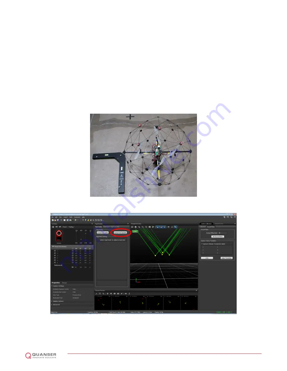
6. Click on the
Create From Selection
button shown in Figure 6.17. The previously highlighted markers now show
up as
Rigid Body 1
, as seen in Figure 6.18.
7. The pivot point of the rigid body must now be moved to the center of the QBall 2. Select the QBall 2 rigid
body in the left side
Project Explorer
pane. While the rigid body is selected, hold the
CTRL
key and select the
top-most marker on the QBall 2 and set it as the pivot point by right-clicking it and select
Set Rigid Body Pivot
Point
, as shown in Figure 6.18.
8. Select the
Orientation
tab in the
Rigid Body
view pane as shown in Figure 6.19. Under
Translation
, set the
Y
translation to
−
0
.
35
m
(negative
35
centimeters from the top point is the center of the QBall 2), as shown in
Figure 6.19. Click
Apply Translation
. The pivot point will move from the top of the cage to the center, as shown
in Figure 6.20.
9. Once the trackables have been defined, they must be saved to a trackables file. This is accomplished by
navigating to
File
|
Save Trackables
.
Figure 6.16: Tracking markers placed for the rigid body
Figure 6.17: Select the markers to create a rigid body object
QBALL 2 - User Manual
DRAFT - April 6, 2015
Содержание QBall 2
Страница 1: ...CAPTIVATE MOTIVATE GRADUATE USER MANUAL QBall 2 for QUARC Set Up and Configuration...
Страница 5: ...Figure 2 2 System diagram QBALL 2 User Manual DRAFT April 6 2015...
Страница 35: ...Figure 6 20 QBall 2 rigid body pivot point moved to the center QBALL 2 User Manual DRAFT April 6 2015...


