background image

Page  22

7014-179K

May 6, 2015

CB 1200 Pellet Stove 

G.  Optional Gold or Nickel Grille Assembly

1. 

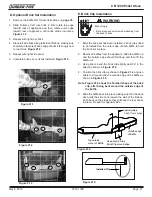
Place the front log in fi rst as shown in 

Figure 22.1

.  Place 

log between fi repot and face of appliance with charred 
area surrounding fi repot.

2.  Set the left and right logs onto the front log, placing  

the holes in the base of the left and right logs over the 
locating pins in front log.  See 

Figure 22.2.

  Ensure that 

the charred ends are facing the fi repot.  

F. Optional Log Set Placement Instructions

CAUTION

Logs are FRAGILE.  Use extreme care when handling or 
cleaning logs.

NOTE:


Due to the abrasive nature of a pellet appliance fi re,  the 
logs are not covered under warranty.  Any placement varia-
tion other than shown here can cause excessive heat and 
shall void the appliance warranty.

LOCATING PINS

Charred Areas in the Back 

Top Log

Right 

Top Log, Left

Front Log 

Figure 22.1

Figure 22.2

Place 1 flap of
box lid into
opening for
stability

CAUTION: Do not open top all the way back so the weight is
supported by the hinges. It will damage the hinges
.  Prop the
top up with supporting brace or use shipping box as shown.

Align the 3 hoes in the stove
with the holes in the grille and
secure in place.

1.  Remove grille from packaging.

2.  Lift top up and place shipping box in vertically.

3. Place 1 fl ap of the box lid into opening for stability.

4.  Align the 3 holes in the stove with the holes in the grille.

5.  Use a Phillips screwdriver to secure in place.

6.  Remove shipping box and lower top.

Install Logo

1.  Remove logo from packaging.

2.  The logo has 2 studs on the back.

3.   Install the logo on the lower left side of the center 

panel by pressing the 2 studs into the pre-drilled 
holes.  

See Figure 22.4.

Do not open top all the way back so the weight of the 
top is supported by the hinges.

  It will damage the 

hinges.  

It will be necessary to prop the top up with 

a supporting brace.  You can use the shipping box as 
shown in Figure 1.

CAUTION

Figure 22.3

H. Installing Logo

Figure 22.4

Содержание CB1200M-MBK

Страница 1: ...to com bustibles as specified Failure to comply may cause house fire Check building codes prior to installation Installation MUST comply with local regional state and national codes and regulations C...

Страница 2: ...ieur de combustion d air doit tre install et ne doit pas tre obstru lorsque l appareil est en usage La structure int grale du plancher du plafond et des murs de la maison mobile doit tre maintenue int...

Страница 3: ...21 F Log Set Placement 22 G Grille Assembly 22 H Logo Installation 22 I Door Installation 23 J Thermostat Installation 23 Section 8 Operating Instructions A Fuel Size Material 24 B General Operation...

Страница 4: ...or approved Improper installation adjustment alteration service or maintenance can cause injury or property damage For assistance or additional information consult a qualified installer service agenc...

Страница 5: ...t termination CAUTION If burning shelled field corn you must use ap proved venting specifically designed for corn to prevent corro sion or degradation Follow the instructions from the venting manufact...

Страница 6: ...uses include Exhaust fans kitchen bath etc Range hoods Combustion air requirements for furnaces water heaters and other combustion appliances Clothes dryers Location of return air vents to furnace or...

Страница 7: ...imney is inspected by a profes sional and is clean or the factory built metal chimney is installed according to the manufac turer s instructions and clearances 9 The chimney meets the required minimum...

Страница 8: ...mm 14 1 4 in 362mm 2 1 2 in 64mm C L 8 1 6 in 205mm 20 7 16 in 519mm 28 1 2 in 724mm 27 5 8 in 692mm 25 3 4 in 654mm C L 10 3 4 in 273mm 24 3 4 in 629mm 25 3 4 in 629mm 8 1 16 in 205mm C L 28 1 2 in 7...

Страница 9: ...orner Installation Inches Millimeters G Walls to Appliance 2 51 B Clearances to Combustibles UL and ULC D E F A B Fire Risk Comply with all minimum clearances to combustibles as specified WARNING Fail...

Страница 10: ...floor protection extending beneath the flue pipe is required with horizontal venting or under the top vent adapter with vertical installation Must extend 2 inches 51mm beyond each side of pipe shaded...

Страница 11: ...ces and protruding parts of the structure P 12 in Clearance above roof line for vertical terminations All minimum clearances are listed with an Outside Air Kit OAK installed unless otherwise noted in...

Страница 12: ...quirements 1 Termination must exhaust above air inlet elevation It is recommended that at least 60 inches 1524mm of verti cal pipe be installed when appliance is vented directly through a wall This wi...

Страница 13: ...an help you calculate the equivalent feet of pipe which is a method used to determine pellet vent size Figure 13 1 D Equivalent Feet of Pipe Example of 3 Elbow Rear Vent Termination Calculation Figure...

Страница 14: ...ot drawn to scale Actual installation may vary due to individual design preference A Alcove Figure 14 1 All minimums listed are to a combustible surface A C B D Alcove Installation Inches Millimeters...

Страница 15: ...ide air kit in mobile homes NOTE In Canada where passage through a wall or partition of combustible construction is desired the installation shall conform to CAN CSA B365 Figure 15 1 Figure 15 2 Wall...

Страница 16: ...A Chimney D Through The Wall Vertical External Firestop Flashing Rain Cap 6 in 152mm Min Non combustible Hearth Pad 3 in 76mm Min Clean out Cover 24 in 610mm minimum Ceiling Support Class A Chimney Co...

Страница 17: ...ry Non Combustible Hearth Pad Airtight Clean out Door Cleanout Cover Sheathing 3 in 76mm Minimum 1 in 25mm Clearance Flashing Fireclay Flue Liner with Airspace Concrete Cap 1 in 25mm Clearance with Fi...

Страница 18: ...ection requirements on pages 9 10 for listings to combustibles and appropriate chimney systems 6 Use silicone to create an effective vapor barrier at the location where the chimney or other component...

Страница 19: ...to outside termination cap with second hose clamp e Secure termination cap to outside surface f Secure trim ring to interior wall g Snip corners and remove plate Figure 19 1 h Align and secure collar...

Страница 20: ...t adapter be sure to silicone all joints 6 To clean the top vent adapter open the clean out cover See Figure 20 1 B Top Vent Adapter Installation Installing the Top Vent Adapter 3 6 Offset Adapter 3 3...

Страница 21: ...n place 2 Remove 2 baffles from the appliance Slide the baffle up and the bottom edge should fall down and then lift the baffle out 3 Using pliers bend the brick clip slightly past 90 in the direction...

Страница 22: ...Place 1 flap of box lid into opening for stability CAUTION Do not open top all the way back so the weight is supported by the hinges It will damage the hinges Prop the top up with supporting brace or...

Страница 23: ...unding prong from plug Plug directly into properly grounded 3 prong receptacle Route cord away from appliance Do NOT route cord under or in front of appli ance CAUTION Power Outlet Terminal Block Cent...

Страница 24: ...the feed rate may require a slight adjustment The BTU output of the appliance varies slightly compared to pellets depending on the quality of the corn used In cases where it is acceptable for the appl...

Страница 25: ...flame height is too high or too low you will need to adjust the feed rate Wait until the appliance has been burning for 15 minutes before making your adjustments and allow 15 minutes for feed adjustme...

Страница 26: ...re Risk Do NOT operate appliance With appliance door open Firepot floor open Cleaning slide plates open Do NOT store fuel Closer than required clearances to com bustibles to appliance Within space req...

Страница 27: ...an Make sure front door is closed Replace control box Call light on No fire Partially burned fuel in firepot Firepot clean out plate not closed Firepot is dirty missed ignition Check that firepot clea...

Страница 28: ...x causing loss of vacuum Empty hopper of fuel Use a wet dry vacuum cleaner to remove remaining fuel from hopper including feed tube Check feed chute for obstructions Loosen 2 screws and jiggle feed as...

Страница 29: ...ss steel baffle from firebox to clean ash from on top of baffle Clean behind rear brick panels Change fuel brand to premium Check that firepot clean out plate is fully closed Reduce feed rate using fe...

Страница 30: ...fuel OR X Ash Pan Corn Daily X Ash Removal from Firebox More frequently depending on the fuel type or ash build up OR X Beneath Heat Exchanger Every 1 ton of fuel OR X Blower Combustion Exhaust More...

Страница 31: ...ing Firepot with Cleaning Rod Firepot Scraper Frequency Daily or more often as needed By Homeowner a Be sure the appliance is allowed to cool has been unplugged and the exhaust blower is off If you ar...

Страница 32: ...heating season By Homeowner a Be sure the appliance is allowed to cool has been unplugged and the exhaust blower is off b To adjust open the latch and pivot the holding rod out Loosen the jam nut on...

Страница 33: ...en the clean out cover See Figure 33 1 c Sweep out any ash build up NOTE There are heavy duty vacuum cleaners specifically designed for solid fuel appliance cleaning Clean Out Cover Figure 33 1 17 Pre...

Страница 34: ...s accumulated in the firebox An inefficient and non economical method of burning of fuel caused by poor quality pellet fuel is shown in Figure 34 2 The correct flame size when good quality premium pel...

Страница 35: ...it up and the bottom edge will fall down and then you can lift the baffle out Repeat for the other side 1 Remove Baffle to Access Heat Exchanger Tubes and Firebox Exhaust Exits 1 Open the upper right...

Страница 36: ...fall down from top frame when removing and replacing center glass a Be sure the appliance is allowed to cool has been unplugged and the exhaust blower is off b Using a nut driver remove the 5 bottom...

Страница 37: ...ined When describing the location of a component it is always AS YOU FACE THE FRONT OF THE APPLIANCE 2 Convection Blower The convection blower is mounted at the bottom rear of the appliance There are...

Страница 38: ...disc 3 is mounted on the back of the auger tube in the right side of the appliance just below the feed motor and has a red reset button To access it remove the feed motor cover box from inside the hop...

Страница 39: ...ocations Heat Output Fan Speed Reset Button Call Light HIGH HIGH MED LOW LOW Power Outlet Terminal Block Center 2 screws for Thermostat Wires Outside Air Flex Hose Convection Blower Cleaning Rods Heat...

Страница 40: ...ce Parts R CB1200M MBK Beginning Manufacturing Date April 2009 Ending Manufacturing Date Active Classic Bay Freestanding Pellet Stove 1 5 2 3 6 7 12 9 8 4 10 11 13 14 15 16 21 17 18 19 20 22 23 24 25...

Страница 41: ...id 200 0110 1 2 Lid Hopper SRV7027 036 Bumper Rubber Pkg of 12 SRV224 0340 12 Y Bushing Hopper Lid Qty 2 812 1010 1 3 Top Assembly Top Only SRV410 4980 Hopper Lid Magnetic Switch 7000 375 Y 2 1 Baf e...

Страница 42: ...410 8320 Y Floor Firepot 414 0290 Y Gasket Firepot 510 0530 Y 10 3 Thermocouple Cover Qty 1 812 1322 Y Pkg of 10 812 4920 Y 10 4 Thermocouple 812 0210 Y 10 5 Thermocouple Bracket W Set Screw 812 3171...

Страница 43: ...Side Curtain Right 410 5261 19 Curtain Side Right 812 3800 20 Latch Draw 229 0640 Y 21 Snap Disc Convection Blower 1 SRV230 0060 Y 22 Convection Blower 130 60 CFM 812 3370 Y 23 Snap Disc 200 Open 40...

Страница 44: ...or distributor Stocked at Depot ITEM DESCRIPTION COMMENTS PART NUMBER 39 Feed Motor Assembly 812 3690 Y Bearing Feed System Nylon 410 0552 Y 39 1 Screw 8 32 X 3 8 PH Pkg of 40 225 0500 40 Y 39 2 Feed...

Страница 45: ...nt Pack Includes Firepot Cleanout Tool Touch Up Paint Power Cord Wire Harness For Thermostat Owners Manual Warranty Card Consumers View Card How To Dvd 812 3630 Cleanout Tool 414 1140 Y Dvd Original E...

Страница 46: ...Air Intake 413 7040 Cover Outside Air Kit Floor 411 1071 Hose Alum Flex 2 Inch x 3 Ft Qty 3 Ft Req 200 0860 Outside Air Cap Assembly 7001 044 Outside Air Collar Assembly 7001 045 Trim Plate Outside A...

Страница 47: ...R May 6 2015 7014 179K Page 47 CB 1200 Pellet Stove E Warranty Policy...

Страница 48: ...Page 48 7014 179K May 6 2015 R CB 1200 Pellet Stove...

Страница 49: ...R May 6 2015 7014 179K Page 49 CB 1200 Pellet Stove...

Страница 50: ...Page 50 7014 179K May 6 2015 R CB 1200 Pellet Stove...

Страница 51: ...R May 6 2015 7014 179K Page 51 CB 1200 Pellet Stove...

Страница 52: ...769426 6774802 6796302 6840261 6848441 6863064 6866205 6869278 6875012 6880275 6908039 6919884 D320652 D445174 D462436 Canada 1297749 2195264 2225408 2313972 Australia 780250 780403 1418504 or other U...

Отзывы: