10
Mounting Option 2
Mounting Option 2 secures the Mounting Bracket to the I/O-22, then the Mounting
Bracket and I/O-22 are mounted to the mounting surface. You can easily remove
the I/O-22 and Mounting Bracket assembly from the mounting surface.
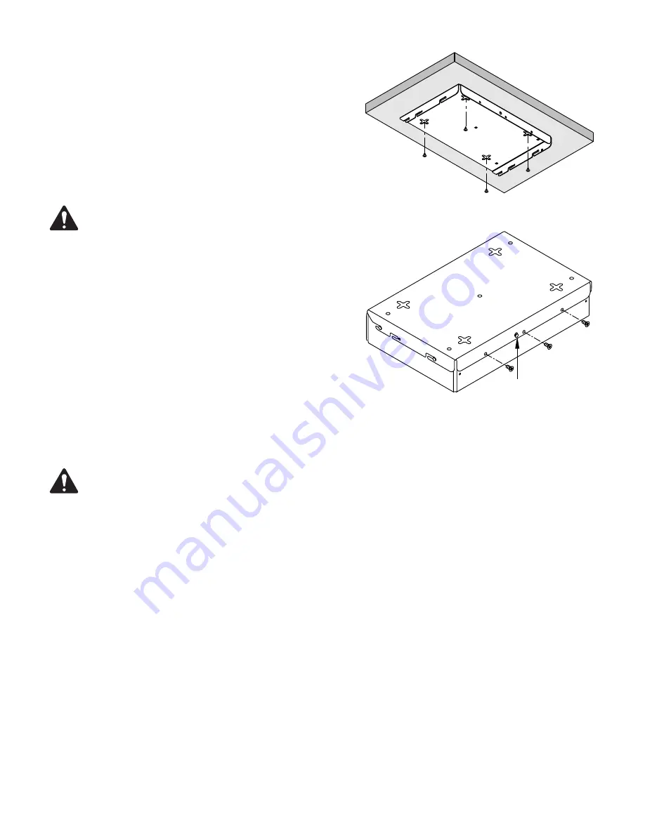
1. Using the Mounting Bracket as a template, mark the four four-way screw slots
(Figure 7)
on the mounting surface.
2. Using an appropriate size drill bit for the screws you are going to use, drill four
holes in the mounting surface in the center of the four-way slots you marked
in step
1
.
ROTE!:
Ensure that the screws have a small enough head to fit
through the center of the four-way slot, yet large enough not to fit
through the slots.
3. Use an appropriate screw driver to install four screws into the mounting surface
leaving enough room between the screw head and the mounting surface to
allow for the thickness of the Mounting Bracket.
4. Prior to assembling the I/O-22 and Mounting Bracket, install the Mounting
Bracket onto the mounting surface to test the fit of the screws and the four-way
mounting slots. You should be able to install the bracket easily, and it should be
snug enough against the mounting surface to prevent accidental movement.
Make any needed adjustments to the screws before continuing.
5. Remove the Mounting Bracket from the mounting surface.
6. Refer to
Figure 6
and complete steps
5
through
7 on page 9
to assemble
the Mounting Bracket to the I/O-22.
7. Install three screws (supplied) through the Mounting Bracket and into the
IO-22 as shown in
Figure 8
. Tighten the screws.
ROTE!:
Depending on the available clearance for your installation, you may connect the cabling before or after attaching the I/O-22 to
the Mounting Bracket.
8. Mount the I/O-22 / Mounting Bracket assembly by aligning the four-way slots with the screws installed in step
3,
pushing the assembly up against
the mounting surface, then slide the unit in one of the four directions provided by the slots.
9. Ensure that the assembly is snug against the mounting surface.
10. Refer to
“Connections” on page 11
for instructions on connecting the cables to the I/O-22 .
— Figure 7 —
— Figure 8 —
1


