QSC DPA-Qn Скачать руководство пользователя страница 11

11

 TD-001585-01-B

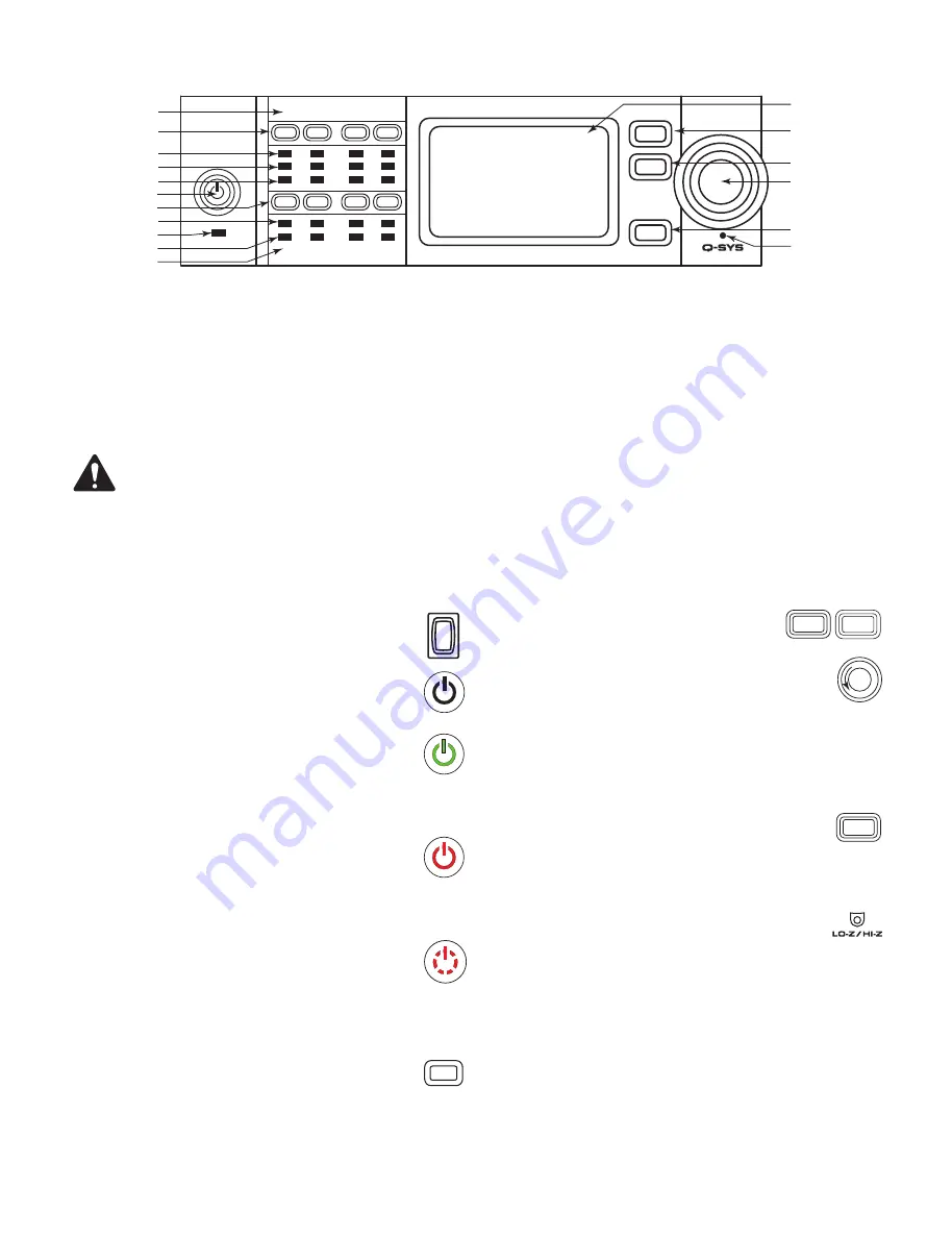
Amplifier Controls and Indicators

— Figure 13 —  

GAIN

A

B

OUTPUT

C

D

MUTE

MUTE

MUTE

MUTE

SEL

SEL

SEL

SEL

LIM

-10

-20

CLIP

SIG

INPUT

1

2

4

3

DPAQ

NETWORK

AMPLIFIER

FAULT

NEXT

PREV

ID

1
2
3

4

5

6

7

8

13

14
15

16

9

10

12

11

17

   DPA-Q 8-Channel Shown  

NOTEE:


The following scenarios assume that the amplifier is connected to the Q-SYS Core via Q-LAN. 

When the amplifier 

is not connected to the Q-SYS Core, it is in a Fault mode, and not operational unless previously configured for fail-over or 
standalone mode as part of a Q-SYS design.


With the exception of the Power Switch, found on the rear panel, all of the following controls are on the front panel. Refer to 

Figure 13

 for 

location of front-panel controls.

1. 

Output Channel labels A, B, C, D, E, F, G, H

2. 

Output Channel Mute buttons / LEDs (Red)

3. 

Output Channel Limiter LEDs (Red) 

4. 

Output Channel -10 dB below maximum 

amplifier output (Blue)

5. 

Output Channel -20 dB below maximum 

amplifier output (Blue)

6. 

Amplifier Mode button (Green/Red)

7. 

Output Channel Select buttons / LEDs (Blue)

8. 

Input Channel Clip LEDs (Red)

9. 

FAULT LED (Amber)

10. 

Input Channel Signal-Present LEDs (Blue)

11. 

Input Channel labels 1, 2, 3, 4, 5, 6, 7, 8

12. 

LCD Graphic Display

13. 

NEXT button

14. 

PREV button

15. 

GAIN Knob

16. 

ID button

17. 

Pinhole Reset

Amplifier Modes

Off Mode 

•  Rear-panel power switch is off, the amplifier is not operable.
•  The Amplifier Mode button (6) is not illuminated.   
•  Turn the power switch to ON. The amplifier enters the mode 

in which it was when power was removed – Run, Mute All, 
or Standby.

Run Mode

•  From Standby or Mute All mode, press and release the Amplifier Mode 

button on the front panel. The amplifier is in Run Mode.

•  The Amplifier Mode button (6) is illuminated green.
•  The amplifier is fully operable; audio can pass.

Standby Mode

•  From Mute All or Run mode, press and hold the Amplifier Mode button (6) 

on the front panel for approximately four seconds.

•  The Amplifier Mode button illuminates solid red.
•  The amplifier is not operable; audio will not pass.

Mute All Mode 

•  From the Run Mode, quickly press and release the Amplifier Mode button 

(6).

•  The Amplifier Mode button flashes red, all output Mute buttons (2) are red.
•  The amplifier output is disabled, but the front panel is fully operable.

Controls

SEL Buttons (7)

•  Output Channel gain can be adjusted from the Q-SYS Designer software or 

from the front panel of the amplifier.

•  Use the SEL button to select one or more than one channel to change gain settings. 

All selected channels will change at the same time. 

•  If two or more outputs are bridged or in parallel, pressing one button in the group 

selects all channels in that bridged or parallel group.

NEXT (13) and PREV (14) Buttons

•  Navigates forward and backwards through the screens.

GAIN Knob (15)

•  Adjusts the Gain for the selected output channel or channels. At least one 

channel must be selected.

•  When one or more channels are selected, turn the Gain knob to jump to the Output 

Gains screen. After a few seconds with no activity, it returns to the earlier screen.

•  If there is more than one channel selected, and the gains for those channels are 

different, the difference is maintained unless the gain is raised or lowered to the limits 
for both channels.

ID Button (16)

•  Press this button to display a screen with the amplifier's network name. In 

addition, the ID buttons on the associated Q-SYS Amplifier component and 
the associated Q-SYS Configurator item flashes. Press again, or click one of the other 
ID buttons, to stop the flashing and exit the screen.

Pinhole Reset (17)

•  Resets the amplifier to its factory default settings.
1.  Insert a paper clip or similar tool into the pinhole
2.  Press and hold for 3 seconds. 
3.  Press the ID button to confirm and reset the amplifier.  

Items reset include: 

•  Network settings set to Auto, 
•  Amplifier name set to default,
•  Password deleted, and
•  Log file deleted. 

Power  
Switch

Amplifier 
Mode  
Button

SEL

NEXT

PREV

ID

All manuals and user guides at all-guides.com

Содержание DPA-Qn

Страница 1: ...work Amplifier with Mic Line Inputs DPA 4K8Q 8 Channel 4000 W Network Amplifier with Mic Line Inputs DPA 8K8Q 8 Channel 8000 W Network Amplifier with Mic Line Inputs DPA 2K4Qn 4 Channel 2000 W Network...

Страница 2: ...any ventilation opening Install in accordance with the manufacturer s instructions 8 Do not install near any heat sources such as radiators heat registers stoves or other apparatus that produce heat...

Страница 3: ...ential installation This equipment generates uses and can radiate radio frequency energy and if not installed and used in accordance with the instructions may cause harmful interference to radio commu...

Страница 4: ...tes that this toxic or hazardous substance contained in all of the homogeneous materials for this part is below the limit requirement in SJ T11363_2006 X SJ T11363_2006 X Indicates that this toxic or...

Страница 5: ...log inputs Item 2a 2b below Figure 1 DPA Q 8 Channel Model Shown 1 2a 3a 3b 4 5 6 2b 7 8 9 10 1 RJ 45 Q SYS Q LAN A B 2 Analog Inputs Mic or Line level 12V Phantom power 3 pin Euro style Connectors a...

Страница 6: ...2 cm clearance Wire Preparation Use an appropriate wire stripping tool to remove 7 mm of insulation from Input wiring and 10 mm of insulation from the Output wiring Do not tin the stripped wire ends...

Страница 7: ...needs or Parallel Mode for higher current needs Figure 7 thru Figure 10 are examples of how the 4 channel amplifier blocks can be combined to drive higher power requirements under different loads Ple...

Страница 8: ...A B C D CHANNEL CONFIGURATION Channel Configuration Locked to Design Q A B Q C Q D BRIDGED T1 T3 CH A B OUTPUTS TO SPEAKERS OUTPUTS TO SPEAKERS CHANNEL CONFIGURATION 4 Channels E F G H Channel Config...

Страница 9: ...el A B Parallel C D Bridged EF G H 2 Channel E F Parallel G H Bridged AB CD 2 Channel A B Parallel C D Parallel EF GH 2 Channel E F Parallel G H Parallel AB CD 1 Channel A B Parallel Bridged with C D...

Страница 10: ...urn the amplifier on 1 Make sure the output gain settings for all audio source devices CD Players Mixers Instruments etc are at the lowest output max attenuation 2 Turn on all audio sources 3 Turn the...

Страница 11: ...approximately four seconds The Amplifier Mode button illuminates solid red The amplifier is not operable audio will not pass Mute All Mode From the Run Mode quickly press and release the Amplifier Mo...

Страница 12: ...LE INPUTS 2 1 4 3 6 5 8 7 MIC LINE 12V Phantom Q LAN Q LAN 5 6 1 2 3 7 4 Q SYS Core 8 Channel Model Shown Amplifier Rear Panel Outputs QSC Loudspeakers Mic Line Input DPA Q Amp Output Amplifier 1 DPA...

Страница 13: ...ware version installed on the amplifier NOTE The DPA Q 4 and 8 channel amplifiers require Version 8 1 0 or later of Q SYS Designer To Update the Amplifier Firmware a Install the version of Q SYS Desig...

Страница 14: ...separation until one reaches a limit At this point the other channel s continue to change until they reach the limit NOTE If you press one or more of the SEL buttons and do not make any GAIN adjustmen...

Страница 15: ...shown 2 Input Level is the Peak Input Level dBFS and is the same as displayed in the Q SYS Mic Line Input component 3 Muted when illuminated indicates that the Input is muted for the associated chann...

Страница 16: ...max 3 3V max 127 resistor in series 9 RELAY NO 1 Relay Normally Open 10 RELAY COM 1 Relay Common 11 RELAY NC 1 Relay Normally Closed 12 GND Ground 13 GPIO 6 18mA in out max 3 3V max 127 resistor in s...

Страница 17: ...annels Combined in Bridged Parallel AB CD Doubles Current Voltage 8 2500 1500 3500 2500 4200 4200 4 3000 1600 4000 2500 7000 4500 2 N R 3 N R 3 N R 3 N R 3 8000 4000 4 Channels Combined in Parallel AB...

Страница 18: ...GH Doubles Current Voltage 8 2500 1200 4000 2400 4 3000 1200 5000 2400 2 N R 3 N R 3 4 Channels Combined in Parallel ABCD or EFGH Quadruples Current 8 1000 1000 1200 1200 4 2000 1200 2400 2200 2 2500...

Страница 19: ...been measured for these specific conditions N A indicates data is not available NR indicates that this configuration is not recommended Peak Voltage Specifications 8 Channel Models DPA 4K8Q DPA 4K8Qn...

Страница 20: ...nob Color Display Fault Indicator Pinhole Reset Controls and indicators rear AC Power Disconnect Locking IEC C 14 AC Power Switch Input connectors DPA Q DPA QN 3 pin Euro green and Q LAN Network conne...

Страница 21: ...h a pink noise signal It approximates operating with music or voice with light clipping and represents the amplifier s typical clean maximum level withou t audible clipping Use these figures for typic...

Страница 22: ...3 212 1 3 Rated Power 1kHz Sine Wave 8 Channel 7 9 6 6 252 3 44 233 860 217 4 Channel 8 7 7 24 316 3 75 293 1079 272 2 Channel 9 6 7 97 405 4 11 379 1382 348 Model DPA 4K4Q DPA 4K4Qn 120 V Mains 230 V...

Страница 23: ...Mute All 1 1 0 9 44 9 0 7 49 153 39 Idle 1 9 1 6 182 0 0 9 184 621 157 1 8 Rated Power Pink Noise 8 Channel 5 4 4 5 455 2 2 421 529 133 4 Channel 6 2 5 2 536 2 5 495 805 203 2 Channel 7 4 6 2 654 3 2...

Страница 24: ...s Monday Friday 7 AM to 5 PM PST Excludes Holidays 1 714 957 7150 1 800 772 2834 toll free U S only FAX 1 714 754 6173 Q SYS 24 7 Emergency Support 1 1 949 791 7722 1 888 252 4836 U S Canada Q SYS Sup...

Отзывы: