


Page 12 of 16 ft8_II_assy_smd_diode_072020.pdf
Trouble shooting:
Soldering issues are the most common reason for a board not to work the first time. A careful
visual inspection will often locate the problem. Ground pads take a little extra heat compared to
other pads, so take note of these. Solder can stick to the component lead, but not flow into the
hole. These bad connections can be hard to spot.
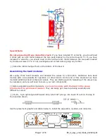
Another problem area is the tinning of the magnet wire used to wind the cores. The wire should
have been tinned before you tried to solder the leads to the board, but sometimes the wire gets
pulled in past the tinned area so the solder doesn't real stick or makes an intermittent connection.
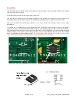
The bifilar wound cores should have continuity between all four pads if the wires are in the right
place. If the pair is reversed, there will only be continuity between the two pads on opposite sides
of the core. If you cannot adjust the PA bias, it is likely T2 is not installed correctly or has a
soldering issue.
Did you do the continuity check of soldering U2?
Double check resistor locations. Make sure you didn't mix up values with similar color codes.
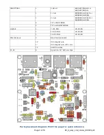
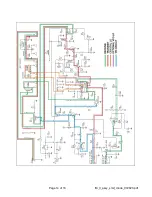
The voltage chart on page 12 can be useful to narrow down a problem area. The exact voltage will
vary a little a little depending on component tolerances and your meter. Only be concerned if the
voltages are significantly different than those shown.
Almost all of the construction issues with the DSB transceiver have been traced to the faulty
installation of T1 or T2. Check carefully the correct orientation of the primary, secondary, tinning
and final soldering of the toroid leads. Double check the T1 and T2 continuity check described
earlier.
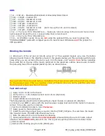
VOX/switching problems:
To test the vox circuit there must be enough audio from the sound card. Check that the computer
is outputting audio to J3. The vertical slider marked (Pwr) on the right side of the WSJT-X
program is the output from the sound card. Moving the slider up should put the transceiver into
transmit, illuminating the LED. In order for the transceiver to enter into transmit mode and the TX
LED to come on, Q5 has to be biased “ON” through R3 and Q4. Q4 turns on when it’s gate is
biased to about 2V. The gate of Q4 is biased to about 2V when the output of U2a (pin1) goes
above about 2.4V. This should take a minimum of 37 mV in respect to ground on Pin 2.
So, where does this go wrong?
Is Pin 1 of U2 high or low?
Low – no problem
High – (~8.5V) check resistors R15, R17, R18 for cold solder connections. Check U2 socket
lead connections to board.
Gate of Q4 high, but Pin 1 low? Check for short across jumper pins and or connection to R7
bad.
Gate of Q4 low, Drain also low? Q4 defective. Verify short with ohm meter.
Gate of Q4 low, Drain high? Q5 Shorted.
Check C11 polarity. If backwards, the cap leakage would trigger U2.
Содержание Digital DSB II Transceiver Kit
Страница 14: ...Page 14 of 16 ft8_II_assy_smd_diode_072020 pdf...
Страница 15: ...Page 15 of 16 ft8_II_assy_smd_diode_072020 pdf...