1
Ultimate LPF kit: Relay-switched LPF kit
PCB Revision 4
1. Introduction
Thank you for purchasing the QRP Labs relay-switched low-pass filter (LPF) kit.
This kit is designed to complement the Ultimate3 QRSS/WSPR kit but could also be used on its own at the
output of a homebrew QRP transmitter. The kit consists of a PCB that switches one of five LPF's between
the transmitter output and the antenna (the kit's “RF output”). This kit does not include the LPF's, it is
designed to accept the plug-in LPF filter kit, which is available separately (for bands 2200m, 600m, and ten
HF bands 160m – 10m).
Note that when used with the Ultimate3 QRSS/WSPR kit, the relay-switched LPF kit provides up to six
bands, each with its own relay-switched LPF. This is because the Ultimate3 kit contains space on its PCB
for fitting Relay 0 (band 0). Combined with the 5 LPF's on the relay-switched LPF kit PCB (band 1 to 5) this
allows for six LPF's.
2. Design
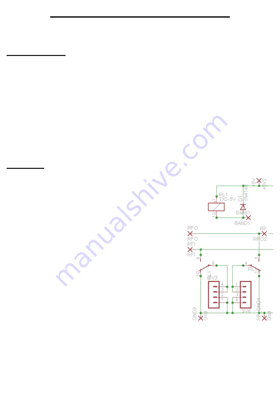
The circuit diagram of one of the LPF switching sections is shown to
the right (band 1). This circuit is simply repeated five times over, on
the relay-switched LPF kit PCB (bands 1 to 5). The same circuit also
exists once on the Ultimate3 QRSS/WSPR kit board (band 0).
Together, they provide six selectable bands for the Ultimate3
QRSS/WSPR kit.
The relay is a DPDT type (dual pole, dual throw). When the relay is
un-energised, the resting position is for both input and output of the
corresponding LPF to be shorted to ground. An LPF kit is plugged in
to the two 4-way sockets, shown here as SV3 and SV4.
When the relay is energised, the corresponding LPF is switched into
the circuit, connected between RF In and RF Out. In use, only one
relay should be energised at once time, to switch in the desired LPF.
The relays are miniature Panasonic RX2-5V types. With a height of
only 8.5mm, they are small enough to fit underneath the plug-in LPF
boards. The coil current is only 28mA and it can therefore be driven
directly by an AVR microcontroller output pin. A 1N4148 diode is
installed across the coil of each relay, to prevent high switching
voltages from damaging the microcontroller output.
The relay-switched LPF kit can be used in your homebrew QRP transceiver project too. One side of the
relay coils are connected to +5V. So to switch a relay, the appropriate band 1 to 5 input should be driven to
a low voltage to energise the relay coil. A transistor could also be used to switch each relay coil.
When used with the Ultimate3 QRSS/WSPR kit, you can either take the RF output from the original
connections on the Ultimate3 PCB, or from connections provided on the relay-switched LPF board.


