December 2022 Rev 4.0 | Subject to change without notice
4 of 20
USER’S GUIDE UG145
Quick Start
Hardware Connections
Refer to Figure 2 for hardware connections.
1. Connect a DC power supply to J8. J8 is connector for input voltage (VIN). Please ensure the correct power supply
polarity.
2. Connect an E-Load to J9. J9 is connector for output voltage (VOUT).
3. Connect Digital Multi-Meters to VIN and VOUT to monitor the input voltage and output voltages.
4. Add a digital Multi-Meter in series with VIN and VOUT if you want to observe input and output current.
5. Be careful to keep the input voltage within the specifications.
6. Optional – Connect the EVK to the PC with the USB dongle.
GUI Setup (optional)
1. Refer to the end of this document for detailed instructions to install the ACT41000 GUI.
2. Connect the USB-TO-I2C dongle to the computer via a USB cable.
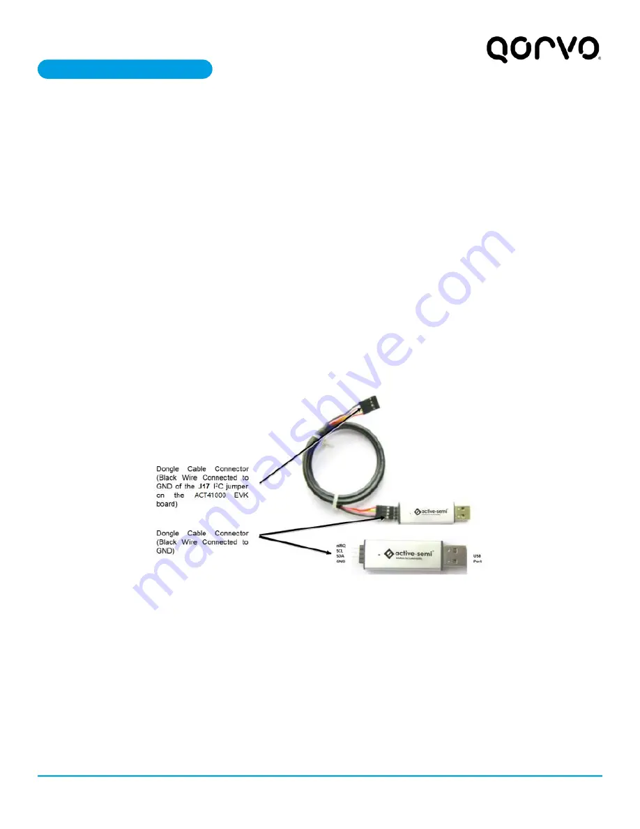
3. Connect the USB-TO-I2C dongle to the EVK J17 connector. Refer to Figure 3 to ensure the correct polarity of the
connection. As a guide, use the “Active-Semi” (or Qorvo) logo on the top of the dongle so the black wire is connected
to the Dongle GND pin.
Figure 3. USB-TO-I2C Dongle Connection
Содержание ACT41000EVK1-104
Страница 3: ...December 2022 Rev 4 0 Subject to change without notice 3 of 20 www qorvo com USER S GUIDE UG145...
Страница 8: ...December 2022 Rev 4 0 Subject to change without notice 8 of 20 www qorvo com USER S GUIDE UG145...
Страница 9: ...December 2022 Rev 4 0 Subject to change without notice 9 of 20 www qorvo com USER S GUIDE UG145...
Страница 18: ...December 2022 Rev 4 0 Subject to change without notice 18 of 20 www qorvo com USER S GUIDE UG145...


