58
4
3. Auto mode. The speed of the air flow in the automatic mode is set up depending on the
level of air contamination, determined by the Dust Sensor.
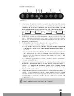
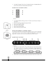
DESCRIPTION OF THE REMOTE CONTROL
1
4
2
5
3
6
Picture 5
1. On / Off Button (When switching on the unit, the clean air outlet louvre will open au-
tomatically).
2. Button for activating and de-activating the child lock
3. Button for setting AUTO MODE.
4. Press to set ventilator capacity.
5. Button for setting SLEEP MODE.
6. Button for setting the timer function.
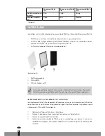
BATTERY REPLACEMENT OF THE REMOTE CONTROL
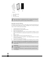
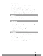
If the batteries of the remote control need to be replaced, remove the cover of the backside
of the remote control, as shown in picture 6. Replace the old batteries by the new ones.
Respect the + and - poles. Don’t use any other batteries than CR2032 lithium 3V.
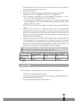
DESCRIPTION OF THE DISPLAY
1
4
2
5
3
6
Picture 8
1. Shows the set ventilator capacity. The ventilator capacity can be set by pressing But-
ton 1 (Figure 4) or Button 4 on the remote control (Figure 5). By pressing this button
repeatedly the capacity of the ventilator will cycle from SLEEP to LOW to MEDIUM and
to TURBO and back to SLEEP again.
SLEEP
LOW
MED
TURBO
2. SLEEP MODE; can be set using the remote control by pressing Button 5 or button 1 of
58
Picture 6
Picture7

