


Page
8
of
18
MANVALTOL-KT2 Rev. A, 6-15-2010
4.4.1.2
Place the wobble gage onto the top of the dissolution
vessel and move the adjustable foot in or out until
the assembly is secured to the inside of the vessel as
shown in Figure #3.
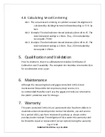
4.4.1.3
With the paddle shaft secured, lower and position the
dissolution drive head so that the dial indicator probe
is located about 2cm above the top of the paddle
blade and adjust the location of the indicator
assembly to establish a pre-load of at least one
revolution of the indicator dial. Tighten the thumb
screws to lock the gage in place. See Figure #4.
Figure #4
4.4.1.4
Set the dissolution tester to 25 RPMs. Start the spindle
rotation and observe the dial indicator travel. Rotate
the dial face so that the minimum counter clockwise
pointer position coincides with “0” on the indicator.
As the shaft rotates, the pointer will move clockwise
to a maximum value. This distance is the total
indicated reading (T.I.R.) or wobble. Each division on
the dial indicator is equal to .01mm.
2cm Above Top of
Paddle Blade
Dial Indicator
Probe


