Qianjiang QJ150T-10 Скачать руководство пользователя страница 1


User's operation and maintenance manual for 

double-wheel motorcycle QJ150T-10   


Zhejiang Qianjiang Motorcycle Co., Ltd   

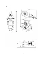
Содержание QJ150T-10

Страница 1: ...User s operation and maintenance manual for double wheel motorcycle QJ150T 10 Zhejiang Qianjiang Motorcycle Co Ltd ...

Страница 2: ... 4 CDI group 45 2 5 Ignition coil 45 2 6 Trigger 46 3 Startup system 48 3 1 Preparation data 48 3 2 Fault diagnosis 49 3 3 Start electric machinery 49 3 4 Start relay 51 4 Bulbs switch instrument 52 4 1 Preparation data 52 4 2 Fault diagnosis 52 4 3 Replace the head light bulb 52 4 4 Replace bulb of the front turning light 53 4 5 Replace the bulb of the taillight 53 4 6 Instrument 54 4 7 Main swit...

Страница 3: ...10 4 Installation of carburetor 85 10 5Adjustment of carburetor 85 11 Cylinder cover air cylinder piston 87 11 1 Preparation data 87 11 2 Fault diagnosis 88 11 3 Cylinder head 88 11 4 Examination on cylinder head 90 11 5 Valve 91 11 6 Examination on valve 91 11 7 Replace the valve guide 92 11 8 Shaping of Valve Seat 93 11 9 Installation 95 12 Crankcase clutch actuating lever 97 12 1 Preparation da...

Страница 4: ...ault diagnosis 116 15 3 Crankcase 117 15 4 Installation 119 16 Cooling system 121 16 1 Cooling system 121 14 2 Fault diagnosis 121 16 3 Thermostat 122 17 Exhaust emission and control system 125 17 1 Warranty of Exhaust emission and control system 125 17 2 Regular maintenance guideline 126 17 3 Mechanical function of the exhaust control system 127 17 4 Catalyst converter system 128 17 5 Countermeas...

Страница 5: ...r I is the explanation of the gist of disassembly assembly and inspection of engine entire vehicle and electric fittings There are exploded view system diagram maintenance fault diagnosis and explanation before each chapter Notice For the universal parts of both types of motorcycle this manual does not seperate the explanation There is no prior individual notification on the alteration of mode or ...

Страница 6: ...unning in a confined place Attention The exhaust contains toxic gas carbon monoxide which can numb people and may result in death The engine should be started in an open area and the exhaust scavenging system should be applied if the engine has to be started in a closed area Gasoline The operation should be made in a ventilated area and smoking or lighting fires should be strictly forbidden in wor...

Страница 7: ...please clean parts and purge it with compressor The operation should not be bended or distorted otherwise it will cause operational difficulties or demage ahead of time The rubber parts will be deteriorated due to aging which is prone to be damaged by solvent or oil and it should be inspected if necessary it should be replaced before reinstallation Loosen the parts with multiple assemblies that sh...

Страница 8: ...uld check the smoothness of oil seal whether it will likely damage the oil seal For the installation of rubber hose fuel vacuum or coolant the ends of which should plug into the bottom of the joint in order to ensure that there is enough space for hose clamp to clamp the joint The rubber or plastic soldering cup should restore its original design position As dismantling ball bearing please use the...

Страница 9: ...th dismounting The list of specific tools for the assembly and dismantling of engine components and the figure of real objects can be seen in table 1 1 and table 1 2 Table 1 1 name remarks Specialized circular wrench Clutch holder Flywheel extractor Spacer gauge Dismounting tools for bearing Assembling tools for bearing Oil seal dismounting tool Handle of dismounting tools Piston pin exhaustion ap...

Страница 10: ... 9 Figure 1 7 Figure 1 8 Figure 1 9 Figure 1 10 手柄 Figure 1 11 Figure 1 12 opening pincer piston Figure 1 13 Figure 1 14 ...

Страница 11: ...netic stand V shape block dial indicator square caliper spring clip ring clipper whack type screw drive front fork oil seal dismounting tools front part seal element driving in tools steering nut wrench Figure 1 19 Figure 1 20 Figure 1 21 Figure 1 22 Figure 1 23 Figure 1 24 Figure 1 25 Figure 1 26 Figure 1 27 Figure 1 28 Figure 1 29 Figure 1 30 1 General tools for the underpan overhaul Successive ...

Страница 12: ... 11 Figure 1 23 Figure 1 24 Figure 1 25 Figure 1 26 Figure 1 27 Figure 1 28 2 Specific tools for underpan overhaul front fork seal element driving in tools Figure 1 29 3 Steering nut wrench Figure 1 30 ...

Страница 13: ...ecific tools for the testing of electric apparatus components as well as the figure of real objects can be seen in table 1 31 and table 1 32 Table 1 31 name remarks universal meter ignition tester Figure 1 33 Figure 1 34 Successive table 1 32 Figure 1 33 Figure 1 34 ...

Страница 14: ...n 120 80 16 Air cleaner paper characteristic Engine Petrol capacity 7 4 0 2L Clutch type Automatism Maximum speed 94km h Climbing capability 20 Transmission CVT Idling speed rpm 1500 100rpm min Gearing Driving mode belt drive Maximum torque 13 3N m 6000rpm Battery capacity type 12V 6Ah dry charged type Maximum horsepower 9 6kW 7500 rpm Generator type QJ 153 2 12V 200W 8500 rpm Compression ratio 11...

Страница 15: ... 14 QJ150 10 ...

Страница 16: ...ne failed to start Spark plug is damp Spark plug is dry Dismantle the spark plug again to re inspect No gasoline in gasoline tank Oil tube clog of gasoline tank carburator Oil tube clog of float chamber Conduitclogofevaporationcontrolsystemoffueltank Gasoline filter clog Auto oil ring is broken Spark plug is broken Spark plug is polluted CDI group is broken Trigger is broken Theleadofsparkingcoili...

Страница 17: ...e or operation Engine overheat Inspect the lubrication of air cylinder head Normal mobile oil level Too much mobile oil Check whether the mobile oil in crankcase is too much or polluted Air cleaner clogged Bad gasoline Conduit clog of evaporation control system of firing chamber Exhaust pipe clogged Auto choke is bad Carburetor vacuum module is broken Auto oil ring is broken CDI group is broken Tr...

Страница 18: ...e and check whether the spark plug has flashover Favorable spark plug flashover Bad spark plug flashover Bad Favorable Intake air in carburetor shim CDI group is broken Trigger is broken Rare gas mixture loosen the bolt Too thick gas mixture locking screw Bad heat spacer shim Loosen fixing nut of carburetor Broken shock insulator Broken suction line Bad or polluted spark plug Bad CDI Bad sparking ...

Страница 19: ...stment Normal Abnormal No clog Clogged Spring broken and slack elasticity Favorable Carburettor clogged CDI group is broken Trigger is broken Too little gasoline in gasoline tank Gasoline filter of gasoline pipe clogged Conduit clog of evaporation control system of fuel tank Auto oil ring is broken Purged Bad spring ...

Страница 20: ...ed line of voltage regulator socket connects to avometer and positive and negative line connects the voltage of motorcycle Check the voltage regulator socket the red line connects universal meter and positive and negative line connect the voltage of motorcycle Improper charging Normal Slack and improper connection Inspect whether the connection of voltage regulator wiring is correct Voltage regula...

Страница 21: ...f CDI group line trap and measure the resistance value Normal Abnormal Abnormal Normal Inspection of related position Inspect whether the CDI group plug is slack Normal Abnor Abnormal Check sparking coil by CDI tester Check CDI group by CDI tester Bad former spark plug Slack spark plug cover Bad contact of plug Main switch is broken Charge coil is broken Trigger is broken Bad sparking coil Main wi...

Страница 22: ...d lamp Battery Clutch Carburator Front rear suspension system Ignition timing Bolt nut fixture Rim tyre Tyre specification Preparation requirement General Warning Before starting engine please confirm whether there is favorable ventilation and do not start engine in a closed location for that the exhaust gas contains carbon monoxide which may numb or kill people Under certain condition gasoline is...

Страница 23: ...r 1 25Mpa 1500rpm Firing time BTDC12 degree 1degree 1500 100rpm Carriage Free stroke of front brake drawbar 10 20mm Free stroke of rear brake drawbar 10 20mm Specification Tire pressure Front wheel 100 80 16 225kpa Tire pressure unit Kpa QJ150T 10 Rear wheel 120 80 16 225kpa front wheel axle clamping nut 55 62 N m Torque force value rear wheel fixed nut 100 113 N m ...

Страница 24: ...ool Shock absorber inspection I I I General purpose tool Bolt inspection I I I I I I Torque spanner Oil leak inspection of gear case I I I I I I General purpose tool Spark plug inspection or replacement I I R R I General purpose tool Replacement of gear case oil I Changed every 5000KM General purpose tool Lubrication of each part L L Lubrication filler Exhaust pipe I I I I I I General purpose tool...

Страница 25: ... the motorcycle is driven on the sandstone road or under the environment of severe contamination the times of purging air filtrator should be increased to prolong the service life 3 For the motorcycle which is frequently driven at high speed or the milage is large the frequency of maintenance should be increased Engine mobile oil filtrator Mobile oil level Attention The motorcycle of which the mob...

Страница 26: ...ment from the filter Check to see if the filter element is polluted or damaged Check whether the filtrator is polluted or damaged Dismantle the clamp component Remove the filter If it is polluted or damaged please replace with new one Check whether the filtrator is polluted or damaged Changing time If the motorcycle is frequently driven on bad road or in rain it should be replaced early Attention ...

Страница 27: ...tle the clamping bar components of battery cell Dismantle the negative lead of prior to the positive lead Take out battery Warning As dismantling positive pole the tools should not contact the carriage in order to avoid short circuit spark and igniting gasoline and the battery will be damaged that will be extremely dangerous The installtion is in the reverse order of dismantling Warning In order t...

Страница 28: ...harge connects to that of battery Warning Fire should be strictly prohibited around battery As starting to charge or upon the completion of charge the switch of charger should be turned off first in order to prevent the sparkle of connecting position from explosion hazard The current time specified on the battery should be the reference for charging Attention If the storage cell is rapidly charged...

Страница 29: ...xed bolt Dismantle the end cover of magnetor Use the ignition timing light to inspect and confirm ignition timing Cylinder pressure It should be made when the engine is warm Remove the guard plate of car body Dismantle spark plug Install cylinder pressure meter Full throttle press Start to run motor and measure the cylinder pressure Compression pressure 1 25Mpa 1500rpm Check the following items if...

Страница 30: ... it is out of clutch and damage Changing gear oil Dismantle the inspection bolt of gear oil Dismantle the oil drain bolt the gear oil will effuse Install the oil drain bolt Attention Confirm the airtightness of bolt and whether it is out of clutch and damage Supplement gear oil Check the oil leak of each position after operation Install the inspection bolt of gear oil Driving chain Dismantle the l...

Страница 31: ...ke handle Free displacement 10 20mm Examination on the liquid amount of the brake liquid When braking to its end check up the oil amount through the oil lens If the liquid level of the brake fluid is vertical to or is lower than the graphic arrow brake liquid should be injected in till the ceiling level Note During the examination the oil pump body should be parallel with the surface Head lamp Rem...

Страница 32: ...heck the actuation Check whether the front shock absorber is leak and each part is loosen Rear Compress the rear shock absorber up and down to check the actuation Check whether each part of the rear shock absorber is damaged or loosened Suspense the rear wheel and swing it to check whether the engine suspension bush is loosened Nut bolt fixture Check whether the bolt nut and fixture of the motorcy...

Страница 33: ...eel 120 80 16 Check whether the front wheel spindle is loosened Check whether the nuts of rear wheel are loosened If so please tighten to specified torque force value Torque force value front wheel axle clamping nut 55 62 N m rear wheel fixed nut 100 113 N m Direction column bearing and handle fixing Swing the handle to check and confirm whether the leads are interfered Turn the front wheel and sw...

Страница 34: ... 33 charging system high pressure bag Lock component for power supply Voltage stabilizer storage battery start up electric engine ...

Страница 35: ...he regulator the battery will have too high voltage which may shorten its service life 3 Long rest of the battery will result in self discharge and the electric capacity will reduce therefore it must be charged every 3 months 4 Inspect the charging system in accordance with the order stipulated in the fault diagnosis table 5 If there is electric current passes through an electrical unit do not dis...

Страница 36: ...xing spanner Fixing bolt of high tension coil 9 0 N m Flywheel dissembler Flywheel fixed nut 5 0 N m Testing instrument Car body guard plate bolt 9 0 N m Avometer 1 2 Fault diagnosis No power supply Discontinuous current Over discharge of battery Poor wiring contact of battery Battery wire not connected Poor contact of discharge system Fuse blown Poor contact or short circuit in lighting system Ba...

Страница 37: ... clamping bar components of battery cell Remove the joint wire of storage cell Measure the voltage between battery terminals Fully charged 13 1V Undercharged 12 3V The battery does not work for an hour Note Inspection of charging state must be performed with a voltage meter 1 3 2 Charge Connecting method Connecting the positive pole of charger and the positive pole of battery Connecting the negati...

Страница 38: ... main wire are in short circuit condition 1 4 2 Inspect the charging state Test with an avometer when the battery is fully charged Mount the fully charged battery after the engine warms up Connect a voltage meter between the battery terminals Connect an amperemeter at the position where two terminals are disassembled to the main fuse Start the engine and measure the clamping voltage and current wh...

Страница 39: ...pens connect the white line terminals respectively white 1 white 2 white 3 The pointer meter indicate a certain value individually otherwise the voltage regulator is damaged and should be replaced 3 The red gauge pen connects the black line terminal of the voltage regulator and the black gauge pens connect the white line terminals respectively white 1 white 2 white 3 The pointer meter indicate a c...

Страница 40: ...ywheel fixing bolt Remove the flywheel with a flywheel puller Disassemble the retaining key Disassemble the lead connector of the alternator Disassemble the alternator stator 1 7 2 Installation Install the alternator stator to the engine case Connect the lead connector of the alternator Clean the tapered part of the crankshaft and flywheel Install the retaining key of flywheel in the key groove on...

Страница 41: ... 40 MAGNETO W W W W G BL W BATTERY MAIN SW SPARK PLUG IGNITION COIL B B W B R BL W W G 点 火 系 统 Lock component for power supply Electric horn Flame ignitor Relay Storage battery Ignition system ...

Страница 42: ...rt is in poor contact or not 6 Inspect whether the spark plug is utilized at a proper thermal value Improper spark plug may lead to unsmooth operation of engine or burn out of the spark plug 7 Inspection in the chapter is based on explanation of peak voltage and the judgment whether the resistance value of ignition coil is OK or not according to records after the inspection 8 Inspection of the mai...

Страница 43: ...t of CDI group when item is abnormal or when there is no spark in the sparkplug side voltage Normal high voltage no spark bad act of spark plug or power leak in secondary coil bad act of ignition coil no high voltage The interior resistance is too low and test it with a designated tester The cranking speed is too low The tester is disturbed if the voltage measured for several times is above standa...

Страница 44: ...and connect the primary coil terminal black white with the diverter at the Ground Press the startup electrical machinery or step on the actuating lever to measure the primary peak voltage of the ignition coil Minimum voltage 95V or above Note The metal area of the avometer prod mustn t be touched by fingers to prevent electroshock 2 3 2 Charge coil Note Install the spark plug on the air cylinder h...

Страница 45: ...r of 6P joint blue white terminal to the wire and the 4P joint black terminal Press the startup electrical machinery or step on the actuating lever to measure the peak voltage of the trigger Connecting method positive pole connected with blue white line and negative pole connected with black line Minimum voltage 1 7V or above Note The metal area of the avometer prod mustn t be touched by fingers t...

Страница 46: ... 5 5KΩ 10 2 5 Ignition coil 2 5 1 Disassembly Disassemble the body guard Disassemble the spark plug cover Disassemble the primary ignition coil Disassemble the ignition coil fixing bolts and unload the ignition coil Installation is conducted in the reverse order of disassembly Note The primary coil is installed in accordance with the black white wire 2 5 2 Inspect the primary coil Measure the resi...

Страница 47: ...ative terminal Standard value 4 5 5 5KΩ 10 20 2 6 Trigger Note Inspection of the trigger can be conducted on the engine Inspection Disassemble the body guard Disassemble the lead connector of the trigger Measure the resistance value between the blue white terminal at the engine side and the body ground Standard value 100 200Ω 20 If the measured value exceeds the standard value replace the alternat...

Страница 48: ...47 启动示意图 BATTERY RELAY BRAKE SWITCH BRAKE SWITCH STARTER SWITCH STARTOR MOTOR Startup diagram high pressure bag Lock component for power supply Voltage stabilizer storage battery start up electric engine ...

Страница 49: ...ngine Please refer to disassembly operation in disassembly Preparation reference Item Standard value Allowable limit Brush length of startup motor 12 5mm 8 5mm Liner of startup idler shaft 8 3mm Outer diameter of startup idler shaft 7 94mm Torque value Bolt in the clutch cover of the startup electrical machinery 12 N m Fixing nut in the clutch of the startup electrical machinery 95 N m Tools Fixin...

Страница 50: ...smantle the bonding strip of the battery and turn on the power supply to see whether the startup electrical machinery will run so as to confirm security First take down the wire clamp of the startup electrical machinery dismantle the fixed bolt of starting motor Separate the front end cover and the rear one Remove the starting motor Roll up the rubber waterproof jacket and disassemble the joint of...

Страница 51: ...d coating of grease Mount the electric brush on the brush holder Spread grease on the active parts of the electric brush ends Press each electric brush into the holder Note Take particular care that the contact surface of the electric brush and armature can not be damaged Take care in case the mounting shaft of the armature should damage the oil seal lip and mount the front cover Install the motor...

Страница 52: ... there is no voltage on the starting relay line inspect the wire and conduction of the brake switch 3 4 3 Inspect the earth line of the start relay Inspect conduction between the gray line at the lead connector terminal and the body ground When pressing the start button the gray line of the connector and the body ground are in good conduction If no conduction occurs inspect the wire and conduction...

Страница 53: ...is pushed to ON but the light doesn t work Bad act of the bulb Bad act of the switch Poor contact of the connector or broken line 4 3 Replace the head light bulb 4 3 1 Disassembly Dismantle the front cover Disassemble the fixing bolts so that the head light could be disassembled Cut off the switch connecter of the head lamp Remove the head lamp Disassemble the air guide sleeve Disassemble the glas...

Страница 54: ... the fixing bolts so that the taillight cover can be disassembled Cut off the switch connecter of the tail lamp Disassemble the taillight 4 5 2 Installation Install the taillight back to the original position in the reverse order of disassembly 4 5 3 Replace the bulb of the taillight 4 5 3 1Disassembly Disassemble the bolts so that the taillight cover can be disassembled Remove the bulb from the s...

Страница 55: ...Dismantle the front guard plate Dismantle the wire joint of the main switch The conduction checking of the joint terminal P 红 白 黄 橙 蓝 红 4 7 2 The replacement of main switch Dismantle the front guard plate of car body Disassemble the setscrews unload the fixing pad of the main switch Disassemble the setscrews and replace the main switch 4 8 Horn Inspection Disassemble the horn wire If the horn ring...

Страница 56: ... 55 4 9 Handle switch 1 light changing switch 2 direction indicator lamp switch 3 bugle switch 4 lamplight switch 5 startup switch PASSING ...

Страница 57: ...screw 4 hexagonal flange clamping nut 5 hexagonal flange bolt 6 seal gasket 7 oil pump body component 8 bolt 9 fixed flat 10 brake switch component 11 screw 12 brake hose assembly 13 brake cylinder component 14 front liquid brake link plate 15 brake clutch component 16 bolt ...

Страница 58: ...bly 5 handle 6 seal gasket 7 hexagonal flange bolt 8 hexagonal flange bolt 9 fixed cover 10 brake switch component 11 cross recessed countersunk flat head screw 12 hexagonal flange clamping nut 13 handle screw 14 rear liquid brake link plate 15 break clutch component 16 rear liquid assembly bolt 17 rear brake tube clamp hoo ...

Страница 59: ...of rear brake pad 6 0 3 0 QJ150T 10 diameter of front hydraulic brake φ240mm Diameter of rear hydraulic brake φ240mm 5 1 2 torque value front rear brake disk fixed bolt 22 29 N m assemble bolt for the front brake cylinder components 22 29 N m assemble bolt for the rear brake cylinder components 22 29 N m 5 2 Fault diagnosis Brake Bad braking quality Slow brake or handle tightening 1 Unfavorable br...

Страница 60: ...ront liquid brake link plate Note Detailed decomposition map can be seen on P56 Note The braking components can not be spoiled by oil stain in installation or disassembly Rinse with stipulated cleaning agent in order to avoid reduction of braking quality Unclamp the fixed bolt of the brake cylinder components antle the following components from the front absorber Disassemble the front wheel spindl...

Страница 61: ...ake ability and invalidate the brake Screw bolt and nut to the stipulated torque force value Torque value Fixing bolt of brake disc 22 29 N m the assemble bolt of front brake clutch components 22 29 N m Keep the brake pad free of oil stain If the brake pad is polluted with oil rinse it with brake cleaning fluid Note Grease on the brake pad may reduce brake ability and invalidate the brake 5 4 Rear...

Страница 62: ...st off the brake disc with 120 sandpaper It must be measured with microcaliper Measure the thickness of brake pad and brake disc If the thickness of brake pad is less than the maintenance value or it is polluted by grease just replace it Note the brake clutch should be replaced in pairs Diameter of rear hydraulic brake φ240mm Height of rear hydraulic brake 4 0mm Allowable limit Brake pad 3 0 mm Br...

Страница 63: ...rake pad and brake disc are polluted with oil rinse them with brake cleaning fluid Note Oil stain on the brake clutch will reduce its performance Note Detailed decomposition map can be seen on P57 Oil pump body component Brake hose assembly Brake cylinder component ...

Страница 64: ...t Box cover component battery cushion component right and front guard plate left and front guard plate foot pedal left and right guard plate helmet box left and right foot pedal cover plate left and right foot p edal rubber left and right foot pedal cover plate left side decorative plate of guard rod Right side decorative plate of guard rod rear interior mudguard right and front guard plate right ...

Страница 65: ...handrail cushion helmet barrel left right and rear guard plate left right and front guard plate rear mudguard rear interior mudguard rear interior mudguard water rubber rear down mudguard foot board front mudguard Note Do not damage any body cover during installation or disassembly Do not damage the knuckle on body cover during installation or disassembly Align the panel and cover plate on the bod...

Страница 66: ...it pin Gear seat component Grooved nut Rolling bearing Front tyre Front wheel ring Middle axial sleeve of front wheel Rolling bearing Oil seal Liquid brake pan Left separating sleeve of front wheel Front wheel axle Installing bolt of liquid brake pan ...

Страница 67: ...n Reference for the entire motorcycle Measuring position Item standard value mm Allowable limit mm front wheel spindle bending 0 2 vertical direction 2 0 front wheel run out of rim transverse direction Within 1 0 2 0 Torque value Tools direction handle fixed bolt 40 60 N m Bearing puller front wheel axial clamping nut 55 62 N m lock in nut wrench 7 2 Fault diagnosis 7 2 1 It s hard to rotate the d...

Страница 68: ... axle and remove the gear seats components and the front wheel Remove bolts and unload the front mudguard and odometer wire Dismantle the bolts and remove the front mudguard and the wires of distance recorder Dismantle the brake hose of the front brake Dismantle the oil seal and bearings by oil seal puller and bearings puller respectively Note the QJ150T 10 forward mounting assemble and dissemble ...

Страница 69: ...ust be punched outward 3 3 4 Installation Smear grease lubricant on the oil seal of the front wheel Smear grease lubricant at the joint part and movable parts of the gear seat components Install the intermediate axial sleeve bearings and oil seal Install the front wheel after involving the gear seat components Note The gear seat components of the mileage table will be deformed if these components ...

Страница 70: ...d lock washer Remove the front fork Tools Direction handle fixed bolt wrench Fixing nut spanner Specific dismounting tools for bearing steel bowl Note Clean the opening part of the body guard board with rags 7 5 3 Installation Tools Fixing nut spanner Rotate the front fork left and right to confirm there is no loosening Steps The installation of direction handle Install the front shock absorber In...

Страница 71: ... is reduced When more than 1 3 radiator flakes are crushed or deformed spillikin pin should be used to shape the flakes The examination on the liquid of radiator Dismantle the radiator cover after making sure that the liquid is sufficiently cooled Completely discharge the cooling liquid Inject the processed cooling liquid into the holes installation hole of the radiator Inject the liquid slowly in...

Страница 72: ... the cover to the cooling system through the radiator cover tester and make sure that the required pressure is lasted for 6 seconds When there s linkage in pressure check up the hose each joint water pump installation point as well as the checking hole of water pump 7 6 3 Installation Carry out the installation according to a reversed sequence of dismantle Radiator cover tester ...

Страница 73: ... 72 Rear wheel rear suspension ...

Страница 74: ...n reference Item Standard value mm Allowable limit mm Vertical direction 2 0 Run out of rear wheel Transverse direction 2 0 Torque value Fixing nut of rear wheel 100 113 N m Topping nut of the rear shock absorber 37 44 N m Bottom nut of the rear shock absorber 22 29 N m 8 2 Fault diagnosis 8 2 1 Run out of rear wheel The rim is distorted tire malfunction the rear wheel is not fastened the tire pre...

Страница 75: ... the rear wheel exceeds the allowable limit the rear wheel bearing becomes flexible which leading to the swinging of the rear wheel Replace the rear wheel bearings with new ones after an examination 8 3 3Installation Carry out the installation of the rear wheel according to a reversed sequence of dismantle and then tighten the nuts rear wheel fixed nut Torque value 100 113 N m QJ150T 10 rear wheel...

Страница 76: ...move the fixing bolts of rear shock absorber Unload the rear shock absorber 8 4 2 Installation Install the rear shock absorber Torque value Upper fixing bolt 37 44 N m Lower fixing bolt 22 29 N m The installation of rear shock absorber The installation of air filter The installation of take in silencer The installation of rear handrail and the rear mudguard The installation of cushion the left rea...

Страница 77: ...scharge bolt Spark plug Mould assembling bolt Variable speed chamber bolt Motor fixing bolt Oil pump fixed bolt Oil pump chain wheel bolt Lock nut of flywheel Right cover stud Double end stud Chain regulator fixed bolt Setscrew of electric wire clamp 25 28 22 25 10 15 10 12 10 12 10 12 10 12 10 12 50 60 10 12 18 22 10 12 4 7 ...

Страница 78: ... 77 Lubrication system figure engine oil strainer oil pump bent axle camshaft piston ...

Страница 79: ...rticles cooling high load parts absorbing impact from the bearing and other parts and reducing noises increasing air tightness between the piston ring and cylinder wall cleaning and carrying away impurities on part surfaces Preparation reference Item Standard Permitted limit when changing the oil 0 9L machine oil capacity when dismantling 1L Dial clearance between the outer and inner rotors 0 04 0...

Страница 80: ...al clutch components loosen the chain cover fixed bolt of the oil pump and take off the chain cover Dismantle the chain wheel fixed nut Lift down the chain wheel and chain Dismantle the bolt and take off the lubricating oil pump components Chain cover Bolt Chain Chain wheel Nut Oil pump Bolt ...

Страница 81: ...al clearance between the inner and outer rotors Allowable limit 0 20mm Examine the clearance between the outer rotor and the oil pump seat Allowable limit 0 21mm Examine the rotor end clearance Allowable limit 0 18mm Oil pump cover Bolt Testing ruler Testing ruler Flat plate ...

Страница 82: ...ter the combination the inner and outer rotors should rotate flexibly with no jamming 9 3 3 Installation Carry out the installation according to the reversed sequence of dismantle Oil pump body Bolt Inner rotor Oil pump chain Oil pump cove Outer rotor Fitting pin Oil pump axle ...

Страница 83: ... inside the float chamber will deteriorate and block the idle speed nozzle resulting in insecurity of idle speed Function of the carburetor the carburetor is a critical component in the fuel delivery system of the engine the operating mode of which carries direct influence on the steady operation of the engine its driving force and economical indicator The carburetor atomizes a given amount of gas...

Страница 84: ...ixture Intermittent flashover in acceleration Bad operation of enrichment valve Too sparse gas mixture Bad operation of needle valve Too high oil level Oilflow in carburetor Air channel blocked Filth in air filter 10 3 Disassembly of carburetor 10 3 1 Disassembly Turn off the switch of the oil tank loosen the oil discharge bolt and take off the fuel hose after letting out the gasoline in the float...

Страница 85: ... damaged or worn down If the needle valve core is damaged or worn down it should be replaced If the needle valve seat is worn down then the carburetor body should be replaced If the float tongue piece is worn down it should be replaced Examine the oil needle of the carburetor to see if it is damaged or worn down If so the oil needle as well as the main nozzle should be replaced Examine the idle me...

Страница 86: ...2000 2500rpm Slowly adjust the mixture adjustment bolts anticlockwise till the engine speed reaches its utmost mixture bolt is withdrawn for two circles at most Reset the idle adjustment screw and set the engine speed down to 1500 100rpm min Pull the throttle for several times for acceleration and inspect whether the idle speed is steady Test the outlet and compare it with the specified standards ...

Страница 87: ... 86 ...

Страница 88: ...on gas of high temperature and high pressure The air intake and air discharge is realized through the valve mechanism Preparation standard Unit mm item standard value allowable limi cylinder pressure 1 25MPa flatness of the cylinder cover 0 03 0 03 take in 0 10 0 12 valve clearance discharge 0 13 0 14 take in 5 00 5 012 5 03 internal diameter of the valve guard discharge 5 00 5 012 5 03 take in 0 ...

Страница 89: ...e valve seat is not good Camshaft is worn down or damaged The filling piece of the cylinder head is of air leakage Camshaft and the valve rocker arm are worn down The installation of park plug is poor Compression pressure is too high Carbon deposit in the combustion chamber is in overabundance 11 3 Cylinder head 11 3 1 Dismantle Loosen the fixed bolt Dismantle the bolt and lift down the chain turn...

Страница 90: ...oken Take off the chain form the driven sprocket Dismantle the camshaft Dismantle the positioning pin Dismantle the cylinder head Note the chain should be hoisted by a section of metal line to prevent it from falling into the crank chamber Spin the M5screw into the rocker arm axle and withdraw the rocker arm axle Dismantle the rocker arm and the decompression apparatus Washer Camshaft M5 bolt Cams...

Страница 91: ...wn If the measuring result is not in accordance with the required value the camshaft should be replaced Allowable limit the height of camshaft take in 29 83mm discharge 29 59mm Measure the outer diameter of the rocker arm axle Allowable limit 9 90mm Measure the inner diameter of the rocker arm axle Allowable limit 10 10mm The clearance between the rocker arm hole and the rocker arm axle Allowable ...

Страница 92: ...5mm When the joint surface flatness of the cylinder cover exceeds its allowable limit fine sandpaper should be put on the flat sheet with the joint surface of the cylinder cover jointed and then push and grind in a 8 form Measure the free length of the valve spring Allowable limit Spring 34 9 mm Ruler Tester Vernier calipers valve oil seal Spring Valve Spacer Spring pan valve lock clip ...

Страница 93: ...lve 0 08mm exhaust valve 0 10mm 11 7 Replace the valve guide Note if the clearance between the valve and the valve guide exceeds the allowable limit valve guide should be replaced After the replacement of valve guide the surface of the portal frame ring of the valve should be conditioned Put the valve guide into the refrigerating chamber of the refrigerator for an hour cooling Use electric furnace...

Страница 94: ...the accumulated carbon in the combustor and cylinder and completely cleansing the inlet and outlet valve Check the width of the contact surface of valve seat the width of valve seat Allowable limit inlet outlet 1 7 mm Allowable limit inlet outlet 1 7mm 11 8 Shaping of Valve Seat Remove the coarse or uneven parts on the surface of the valve seat by using the milling cutter of 45 Note paint a transp...

Страница 95: ... uneven parts Standard width of valve seat Inlet 1 2m Outlet 1 2m If the contact part is the higher part of valve use the plain milling cutter of 20 to lower the valve seat If the contact part is the lower part of valve use the internal milling cutter of 60 to lower the valve seat Use the refining milling cutter of 45 to refine the valve seat so as to make it fit the required specifications After ...

Страница 96: ...ly Note when installing the valve spring put the spring end with a shorter pitch towards the combustor When install the valve lock use the compressing tool of valve spring When install the valve paint proper engine oil on the surface of the valve stem and then put it in the valve guide ...

Страница 97: ... 96 ...

Страница 98: ...stion chamber with the cylinder cover and others Preparation reference Unit mm Item Standard value Allowable limit internal diameter 57 50 57 413 57 513 cylindricity 0 004 0 004 roundness 0 005 0 005 Air cylinder flatness 0 05 0 05 piston mark direction IN properly opposite to the inlet valve measuring point of the piston s external diameter 57 465 57 485 at the bottom of the piston skirt 7mm 57 4...

Страница 99: ... is too much in the combustor The air cylinder piston and piston ring is worn out The piston pin hole and piston pin are worn out 12 3 Cylinder body 12 3 1 Disassembly of air cylinder body Dismantle the cylinder head the gasket of the cylinder cover and the guide pin Dismantle the leading chain plate Dismantle the cylinder 12 3 2 Inspectionof air cylinder body Inspect the wear and tear of the cyli...

Страница 100: ...ean away the carbon deposit in the piston ring groove Install the piston ring Measure the clearance of the piston ring and piston ring groove Allowable limit Top ring 0 10mm Second ring 0 10mm Unload the piston ring and install each piston ring at the bottom of the cylinder Note Press the piston ring into the air cylinder with the piston crown Measure the interface clearance of the piston ring All...

Страница 101: ...ring position and the piston pin form an angle of 90 degree some 7mm below the skirt of piston Allowable limit 52 37mm Inspect the abrasion and wear of the cylinder inner wall Note Measure the bore diameter of the cylinder at the upper middle and lower part when keeping an angle of 90 degree from the piston pin Allowable limit 52 413mm Measure the clearance of the cylinder and piston and take the ...

Страница 102: ...it 0 05mm Measure the bore diameter of connecting rod small end Allowable limit 14 04mm 12 5 Installation of piston Install the guide pin Paint the engine oil on each piston ring and piston Install the piston in the right place with the mark of piston ring upward Note The piston should not be scratched and the piston ring should not be broken After installed the piston ring can rotate freely in th...

Страница 103: ... and retaining ring Note Install the piston with the IN mark on the piston top towards the inlet valve 12 6 Installation of the air cylinder Install the gasket and guide pin on the crankcase Evenly spread machine oil on cylinder inner wall piston and piston ring Take care to install the piston ring in the cylinder Note The piston ring should not be damaged gasket gasket guide pin cylinder IN mark ...

Страница 104: ... 103 ...

Страница 105: ...02 28 04 the external diameter of sliding sleeve 23 967 23 98 23 98 width of the triangle belt 21 2 22 8 22 8 thickness of the friction plate of clutch 1 5 1 5 the internal diameter of outer sleeve of clutch 125 125 2 125 5 the free length of clutch pressing spring 69 1 70 the external diameter of right half shaft sleeve of the driven wheel 42 92 42 98 42 90 the external diameter of right half sli...

Страница 106: ... Dismantle the fixing nut of the drive disk and take down the left half of the drive disk Take down the triangle belt from the drive disk Check whether the triangle belt is chapped and whether the rubber and cotton yarn fall off or are abnormally worn out Measure the width of the triangle belt Allowable limit 22 8mm Note when replacing select the original parts width left cover fixing bolt gasket ...

Страница 107: ...ponents of the drive wheel Decompose the right half components of the drive wheel Check the abrasion of the ball bearing Measure the external diameter of the ball bearing Allowable limit 19 5mm Right half components of the drive wheel ...

Страница 108: ...ter part of clutch with the fixing tool and dismantle the fixing nut Take down the outer part of clutch clutch driven wheel 13 5 2 Decomposing the clutch Dismantle the check ring and decompose the clutch Note when decomposing there should be no grease adhesive to the friction plate of clutch Friction plate Retainer ring Box wrench Clutch coating Driven wheel Fixer Right half components of the driv...

Страница 109: ...e the clutch and the driven wheel When dismantling the clutch pressing spring use the clutch spring compressor in the operation Note the spring compressor must be used in dismantling to prevent damaging the spring Fix the spring compressor and dismantle the fixing nut of clutch Loosen the compressor and decompose the clutch and driven wheel Take down the protective jacket of the spring Friction pl...

Страница 110: ...e limit 42 90mm Measure the internal diameter of the left half sliding sleeve of the driven wheel Allowable limit 34 00mm 13 6 1 Replacement of the right half bearing of driven wheel Take down the needle bearing from the right half driven wheel Dismantle the elastic check ring and the outer rolling bearing Note The dismantled nearing can not be used again Rolling bearing Elastic check ring Needle ...

Страница 111: ... needle bearing 13 6 2 Combination of clutch and driven wheel Clean the grease on the driven wheel surface Install the oil seal in the left half sliding sleeve of the driven wheel Paint grease on the O typed ring and install it on the left half sliding sleeve of the driven wheel Combine the left half and right half parts of the drive wheel Paint grease on the guide pin install in the guide slot Gu...

Страница 112: ...e clutch spring to compress and compose After compression install the locking nut Note the spring should be compressed properly Otherwise the spring will be damaged 13 7 Installation The order of assembling the driven disk clutch and driven wheel is opposite to that of disassembly Clutch spring compressor Wrench locknut Protective jacket of the spring ...

Страница 113: ... 112 Output axle Middle axle Input axle ...

Страница 114: ... determine the torque and rev of the final output 14 2 Fault diagnosis The motor can not move when the engine is started The drive gear is broken The drive gear is burnt out The gear oil is leaked The gear oil is too much The oil seal is damaged 14 3 Gear Case 14 3 1 Disassembly Loosen the bolt and take down the gear case cover Bolt Gear case cover ...

Страница 115: ...ition is serious replacement is necessary Dismantle the oil seal on the gear case and push out the bearing Note The bearing which is pushed out can not be used and should be replaced The disassembly of bearings and oil seal should use special tools 14 4 Installation The order of assembly is opposite to that of disassembly Note Bearing Bearing oil seal Middle axle combination Input axle Output axle...

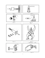
Страница 116: ... 115 The assembly of bearings and oil seal should use special tools to prevent damage ...

Страница 117: ...e cylinder cover and bearing bursting impact of combustion and movement inertia force of crankshaft connecting rod system and constituting some closed oil air seal space The crankcase has a hanging hole which links the engine and the frame with other parts by connecting with the hanging hole Preparation reference Unit mm Item Standard value Allowable limit clearance of connecting rod big end in ri...

Страница 118: ...tool Take down the magneto Take down the starting indolent gears and shaft Dismantle the bolt and the sprocket end cover of the engine oil pump Dismantle the engine oil pump Dismantle the right crankcase bolt Put the left crankcase in the bottom and dismantle the right crankcase Right crankcase Bolt Chain wheel cover Gasket Magneto Locknut Starting indolent gears Bolt Right crankcase cover ...

Страница 119: ...irection Allowable limit 0 55mm Clearance measurement of connecting rod big end in X and Y direction Allowable limit 0 05mm Inspect whether there are strange noises or loosening in rotation of the crank shaft bearing If there is strange noises or loosening replace the crankshaft set measuring position of connecting rod big end Crankcase bearing Positioning pin Gasket Crankcase connectin g rod asse...

Страница 120: ...not be used again The dismantling of the oil seal should use special tools 15 4 Installation The order of assembling crankcase is opposite to that of the disassembly Note The installation of oil seal should use special tools in order to prevent the damage against the oil seal Oil seal ...

Страница 121: ... 120 Cooling System Diagram thermostat water inlet mouth water outlet pipe water inl et mouth Pump ...

Страница 122: ... The radiator cover should not be dismantled except for complementing again the radiator liquid after the cooling system is dismantled or for extracting the radiator liquid 3 The cooling system can be maintained on the motor 14 2 Fault diagnosis The cooling water is little The engine is too hot the water is evaporated or leaked the cooling cycle is not good the soft water pipe is broken or aging h...

Страница 123: ...e within 3 min Radiator When radiating fin over 1 3 of radiator is damaged or distorted it needs to be repaired by spillikin pin Switch subassembly for waterexit Conduction temperature 93 C 2 C Return temperature 88 C 2 C Initial startup temperature 72 84 C Full open temperature 93 96 C Lift in full open state Over 4 27mm Switch subassembly for waterexit Radiator fan O type ring Thermostat room bo...

Страница 124: ...ched infuse from infusing hole Examination of pump Make sure whether the mechanical seal is damaged or not from leakage examining hole if coolant is leaked from the leakage examining hole the mechanical seal is damaged and the whole pump should be replaced For the pump possible to be discomposed replace the mechanical seal Pump Checking hole for liquid leakage Outtake pipe Intake pipe Cover part c...

Страница 125: ... 124 Muffler ...

Страница 126: ...is not applicable but maintenance and service at a reasonable price will be provided to customers by our dealers or service departments at province or city level 1 Regular maintenance is not performed in accordance with the specified time or service kilometers by our Company 2 Those who do not have regular inspection adjustment or service at our dealers or service centers or who fail to bring forw...

Страница 127: ...imized vehicle conditions Note Increase cleaning times of air filter if the motorcycle is used on sandstone roadways or in severely polluted environment so that service life of the engine may be extended When the vehicle is driven at high speed or in frequent use with considerable service kilometers its maintenance degree should be increased Ensure the emission standards and pay attention to the f...

Страница 128: ...n time such improvement in exhaust system alone has achieved high intake and exhaust efficiency which enables increase of combustion efficiency Air induction device Introduce the air into the vent pipe so that the CO and HC incomplete combustion could be turned into innocuous gas in the second reaction Difference Device Constituting part Objective and function Exhaust system Catalyst device Cataly...

Страница 129: ... shortly after it is started or stalled 2 Keep the vehicles loaded with catalyst converter away from inflammable materials 3 The vent pipe contains CO that does harm to health therefore don t run the engine in enclosed space 4 The vehicle loaded with catalyst converter can not use leaded gasoline To guard against catalyst poisoning 5 do not start the engine by pushing the vehicle If startup must b...

Страница 130: ... engine valve leak piston wear combustion chamber Qualified for delivery Qualified Qualified Qualified Qualified Qualified 17 5 Countermeasure of idle speed emission exceeding specified value four stroke Remark 1 Measure with idle speed measuring procedure Remark 2 Adjust the engine speed within the stipulation with a set screw and measure idle speed CO HC Meanwhile adjust the air bolt so that CO ...

Страница 131: ... 130 ...

Отзывы: