C
ONNECTING
A
F
IBER
-
OPTIC
C
ABLE
I
NSTALLING
H
ARDWARE
2-11
4. Turn the cap from the gland body and remove it.
5. Lift the locking mechanism to unlock the protective cap at the end of the gland
body, and remove the cap.
6. Before inserting a cable, disassemble the gland cap, the gland seal, and gland
rubber from the gland body.
7. Assemble the cable in the gland body using the following guidelines:
a. Split the connector into two separate LC connector.
b. Slide gland cap into the cable.
c. Insert the gland seal over the cable.
d. Insert the gland rubber over the cable.
8. Insert the wire with the connector into the cable gland. Insert the second wire in the
same manner.
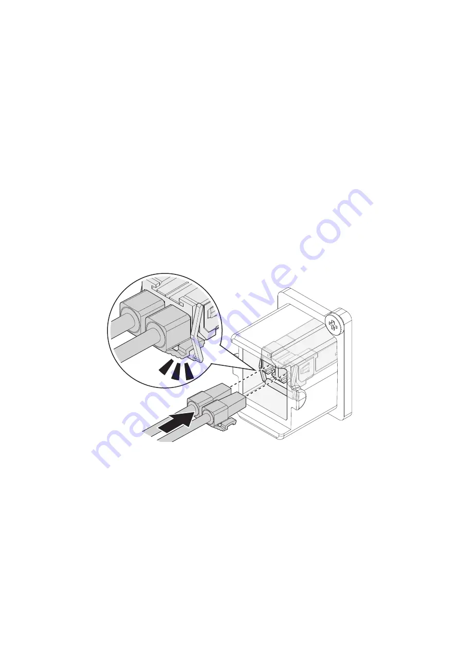
9. Before proceeding make sure the SFP transceiver is installed in the device. Connect
the cable to the SFP transceiver. Ensure an audible click sounds signifying a correct
installation.
Figure 2-13.
Connecting the Fiber Cable to the SFP Transceiver
10. Slide the gland body assembly into the SFP port until it is flush in the port.
11. Slide the gland rubber, gland seal, and gland cap into the gland body. Ensure there
is no excess cable. The waterproof gland is flush in the SFP port when seated
correctly.
12. Close the locking mechanism on the gland body to lock the gland body in place.
13. Tighten the gland cap. If necessary, use a wrench to tighten to a torque of 2 ~ 2.5 N-
m (17.70 ~ 22.17 lbf-in.).


