38
39
CHAPTER 4 MAIN MENU SETUP
VIDEO LOSS
In the event that signal is lost by one camera, others can be activated to record while
additional devices can also be triggered.
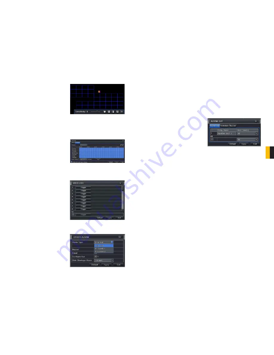
Click on the icon showing a silhouette of a
person and an illustration of a walking figure
will appear on the screen. Test your settings
by dragging the figure across the blue grid to
see if the sensitivity value and motion area are
suitable to current conditions. If they are, click
the
o
icon to save before exiting using the
X
button.
Right-clicking in the screen will show or hide
the menu at the bottom of the screen.
Schedule Tab
This is also set to be on all the time by default and it can be adjusted in the same manner as
the
Schedule
configuration in
SECTION 4.4.
PICTURE 4-30
PICTURE 4-31
PICTURE 4-32
PICTURE 4-33
Like the
Trigger
tab in the
Alarm Handling
section of the
Sensor
menu, you can select
the events that you wish to occur in the
event that a video input is lost. Both Alarms
and PTZ events can be scheduled as in the
Sensor
menu above.
OTHER ALARM
In this menu you can set the DVR to alert you to a full Hard Drive, IP Conflict on the network or
a Disconnection.
You can set the response as well as at what
threshold of remaining disk space you wish to
be alerted.
ALARM OUT
Set how the alarms are handled and transmitted in this window. This controls any device
attached to the ALARM OUT port on the back of the DVR. There are three tabs;
Alarm Out
,
Schedule
and
Buzzer
.
Alarm Out Tab
You can set the relay alarm out name as well as the hold time. Hold time is the interval
between consecutive alarm activations so multiple events within the interval will not cause the
alarm to sound again.
Schedule Tab
The default setting is for the ALARM OUT to be active all the time, but this can be changed
to meet your particular requirements in a similar manner to
Schedule
in
SECTION 4.4
.
Buzzer Tab
As with the
Alarm Out
hold time, the internal buzzer can be enabled and given a hold time.
PICTURE 4-34


