


66
67
Date & Time Tab
Set date, time, time format and related configurations in this menu.
PICTURE 4-5
PICTURE 4-6
System
System
DST
DST
Date & Time
Date & Time
BASIC
BASIC
Default
Default
Apply
Apply
Exit
Exit
Update Now
Update Now
Save Now
Save Now
Date Format
Time Format
Time Zone
Sync Time with NTP Server
NTP Server
System Date
System Time
25
MAY
MM-DD-YY
24 Hour
GMT
time.windows.com
03/04/2011
12 : 43 : 13
MM-DD-YY
24 Hour
GMT
time.windows.com
03/04/2011
12 : 43 : 13
Date Format
Time Format
Time Zone
Sync Time with NTP Server
NTP Server
System Date
System Time
Date
System
System
DST
DST
Date & Time
Date & Time
BASIC
BASIC
Default
Default
Apply
Apply
Exit
Exit
Daylight Saving Time
Time Offset [Hours]
Mode
From
Until
1
March
The 2nd
Sunday
02:00:00
November
The 1st
Sunday
02:00:00
1
March
The 2nd
Sunday
02:00:00
November
The 1st
Sunday
02:00:00
Daylight Saving Time
Time Offset [Hours]
Mode
From
Until
Date
Week
Week
This setting allows your system to adjust for time changes due to Daylight Savings Time.
Again, your system must be connected to the Internet for this feature to work. As of this
writing, Daylight Savings Time begins in most areas of North America on the 2nd Sunday
in March and ends on the first Sunday in November. Both changeovers happen at 2 am.
Allowing the DVR to make the change automatically ensures that files will not be lost as could
happen by manually changing the hour.
Checking the box marked
Daylight Saving
Time
will enable the DVR to switch the hour
automatically.
The starting and ending periods must be
set using the pull down options along with
entering the hour manually. The
Week
radio
button should be selected for this method.
If your region switches to and from DST on
a specific date, then chose the
Date
radio
button and enter the needed information.
Click
Apply
to save your settings and
Exit
to
close the menu.
Setting the correct date and time before proceeding is essential to maintaining the integrity
of your video records - especially for purposes of evidence. Making these straightforward
settings should be your first priority before proceeding further within this manual. Changing the
date and time after important videos have been recorded could result in the loss of those files.
IMPORTANT!
To maintain the integrity of recorded video, you should set
the DVR to the correct date and time before making changes in other menus.
Most of the options within this menu are
self-explanatory. If you are unsure of your
time zone, the date and time settings on
your computer or searching online for “Time
Zones” will quickly provide you with the
information you need.
NTP Server:
Using Network Time Protocol
will keep your system’s clock current
by allowing it to occasionally receive
updates from the selected server.
Your DVR must be connected to
the Internet for this feature to work.
Please see the Remote Monitoring
Guide for instructions.
DST Tab
4.2 LIVE CONFIGURATION
Live configuration includes four submenus:
Live
,
Main Monitor
,
Spot
and
Mask
.
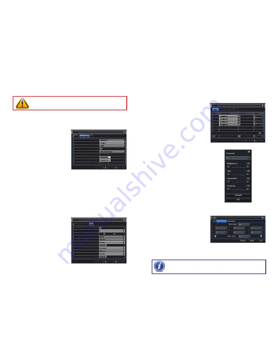
Live Tab
Use this menu to set camera names and adjust picture colors, brightness, hue saturation and
contrast for optimal picture results.
Live
Live
Spot
Spot
Mask
Mask
Main Monitor
Main Monitor
LIVE
LIVE
Default
Default
Apply
Apply
Exit
Exit
Setting
Setting
Setting
Setting
Setting
Setting
Setting
Setting
Setting
Setting
CH
Camera Name
Show Name
Color
1
2
3
4
CH
Camera Name
Show Name
Color
1
2
3
4
CAMERA01
CAMERA01
CAMERA02
CAMERA02
CAMERA03
CAMERA03
CAMERA04
CAMERA04
All
Recording Status
All
Recording Status
PICTURE 4-7
PICTURE 4-8
You can individually name cameras by
highlighting the field for each camera. The
virtual keyboard will appear allowing you to
enter characters, numbers and symbols with
case sensitivity.
ENTER
will save the name
and return to the
LIVE
menu.
ESCAPE
will
exit the keyboard without saving.
You can enable or disable the display of the
cameras’ names and recording status (
see
Section 3.3
) by using the check boxes.
Main Monitor Tab
Select the configuration of your display.
Split Mode allows you to choose from
single view, 2x2, 2x3, 3x3, 4x4
(depending
on model)
views on a screen at one time.
You can also select which channels will be
displayed.
Channels can be grouped and the display will
cycle between groups. Any individual channel
can be shown in more than one group.
Dwell Time:
This is the time interval the
display will spend showing a group
before moving on to the next group.
NOTE!
If viewing remotely on a computer with dual monitors, the display must
be on the main monitor.
PICTURE 4-9
You can configure the color settings for each
channel individually. Adjust image saturation,
hue, brightness, and contrast by clicking on
the Setting button for each individual camera
or for all of them simultaneously by selecting
the All button before making the settings. This
window can also be reached by clicking the
color button on the
Control Bar
.


