13
Assembly and installation manual
QIM/QDB Mixer Series
QIM/QDB-M01
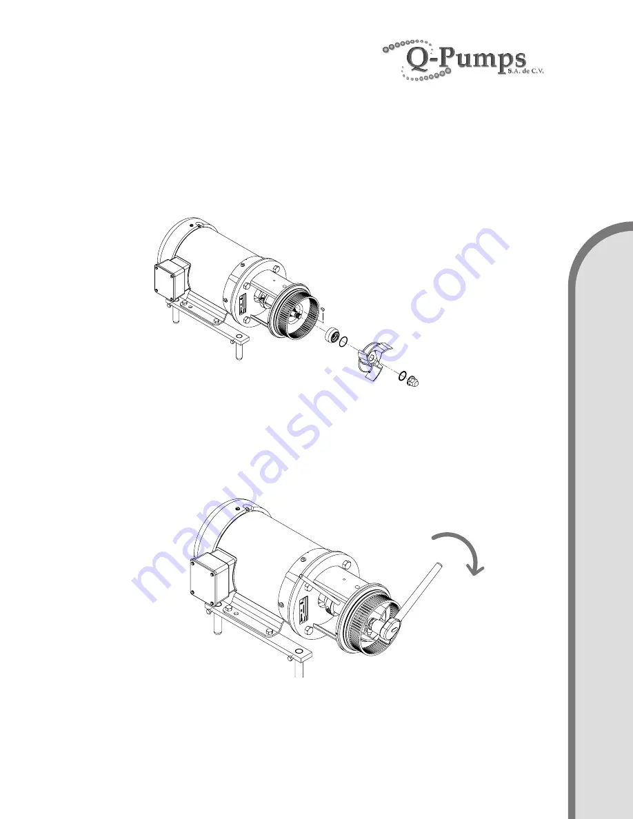
3c. Put the impeller key (24C) on the keyway of the stub shaft. Place only the rotary holder
of the mechanical seal (96A) together with its respective O-ring (96E) until it seats on the
shoulder of the stub shaft. The impeller key does not interfere with the mechanical seal
drive collar.
Take the impeller nut (24D) and place the impeller gasket (91B) on it, then place the impeller
in the stub shaft and tighten with the impeller nut compressing the assembly. Figure F.
Use a 5/8” hexagonal socket for models 114 and 214 and a 7/8” hexagonal socket for the
rest of models to tighten the nut.
To prevent the stub shaft-impeller assembly from turning you can use a Ø3/8” rod in the
bore that has the stub shaft on its side and thus be able to tighten or loosen the impeller
nut. Figure G.
Remember that you can use water or dishes soap to lubricate or glue O-rings and
gaskets to the metal elements to facilitate assembly.
Figure F.
Figure G.
A
SS
EM
B
LY


