48
© 2008 Directed Electronics. All rights reserved.
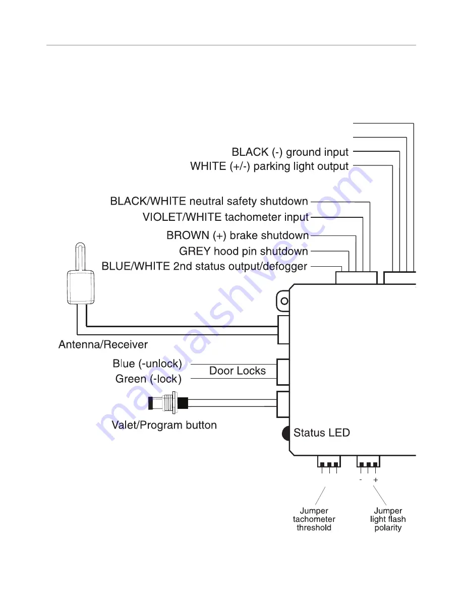
Wiring quick reference guide
ORANGE (-) ground when locked (Not used)
BROWN (-) horn honk output
red 4 pin d2dbitwriter port
VIOLET
Off On
RED/WHITE (-) 200mA channel 2 output (Not used)
Страница 1: ...ntended for installation by a profes sional installer only Any attempt to install this product by any person other than a trained professional may result in severe damage to a vehicle s electrical sys...
Страница 2: ...requires the T harness included in the Bitwriter chip version 2 6 kit 998U Bitwriter Code Hopping Doubleguard ESP FailSafe Ghost Switch Learn Routine Nite Lite Nuisance Prevention Circuitry Reveng er...
Страница 3: ...pin connector 14 Heavy gauge relay interface 20 Remote start harness H2 5 pin connector 21 Neutral safety switch interface 24 D2D and programmer interface 25 Programming jumpers 26 Light flash 26 Plu...
Страница 4: ......
Страница 5: ...pment does cause harmful interference to radio or television which can be determined by turning the equipment OFF and ON the user is encouraged to try to correct the interference by one or more of the...
Страница 6: ...is the user s sole responsibility to properly handle and keep out of reach from children all remote controls to assure that the system does not unintentionally remote start the vehicle USER MUST INST...
Страница 7: ...The remote start module must be removed or properly reinstalled so that the vehicle does not start in gear All installations must be performed by an authorized Directed Electronics dealer OPERATION O...
Страница 8: ...rights reserved What is included The control module see diagram Responder One transceiver P N 6212T Two 2 way remotes P N 7211P A push button programming switch A hood pinswitch A shut down toggle swi...
Страница 9: ...logic probes computer safe test lights Test all circuits with a high quality digital multi meter before making connections Do not disconnect the battery if the vehicle has an anti theft coded radio If...
Страница 10: ...king voltage of the vehicle using a very fast micro controller and an analog to digital converter The micropro cessor saves the base voltage as a reference When Virtual Tach sees the slightest uptick...
Страница 11: ...cceptable ways of making a wire connection solder connections and crimp connectors When properly performed either type of connection is reliable and trouble free Regardless of whether you solder your...
Страница 12: ...EASE OUTPUT H1 8 BLACK GROUND H1 9 WHITE LIGHT FLASH not available with 1 button remote 4 pin satellite harness wiring daigram 1 BLUE STATUS OUTPUT 2 ORANGE ACCESSORY OUTPUT 3 PURPLE STARTER OUTPUT 4...
Страница 13: ...OT USED 3 GREEN LOCK OUTPUT Ignition controlled lock only Remote start harness H2 wiring diagram H2 1 BLACK WHITE NEUTRAL SAFETY SWITCH INPUT H2 2 VIOLET WHITE TACHOMETER INPUT WIRE H2 3 BROWN BRAKE S...
Страница 14: ...ALARM DISARM This wire sends a negative pulse every time the remote start is activated or the doors are unlocked This can be used to pulse the disarm wire of the vehicle s factory anti theft device U...
Страница 15: ...r pulse to the arm wire H1 3 YELLOW IGNITION OUT TO ALARM As a stand alone system The H1 3 YELLOW wire should not be con nected to anything As an add on car starter If connected disconnect the ignitio...
Страница 16: ...tivation pulse count can be programmed to 1 2 or 3 pulses when changed it will affect both activation inputs the White Blue wire and the remote control activation OPTIONAL MOMENTARY SWITCH H1 5 ORANGE...
Страница 17: ...tem Note the honk upon locking and panic features are not available with the 1 button remote H1 7 RED WHITE trunk release 200 mA output When the system receives the code controlling trunk release for...
Страница 18: ...ake your own ground with a self tapping screw and a star washer H1 9 WHITE LIGHT FLASH OUTPUT Important Do NOT connect this wire to a negative vehicle light flash wire before changing the program ming...
Страница 19: ...s that draw 10 amps or more the jumper must be placed to the light flash output refer to the Program ming Jumpers section of this guide P N 8617 or a standard automo tive SPDT relay must be used on th...
Страница 20: ...e 3 ORANGE 30 AMP OUTPUT TO ACCESSORY CIRCUIT Connect this wire to the accessory wire in the vehicle that powers the climate control system 4 6 RED 30A HIGH CURRENT 12 INPUT Remove the two 30 amp fuse...
Страница 21: ...the other wire from the toggle switch to the park neutral switch in the vehicle This wire will test with ground with the gear selector either in PARK or NEUTRAL This will prevent the vehicle from acci...
Страница 22: ...tioning properly H2 2 VIOLET WHITE TACHOMETER INPUT WIRE This input provides the module with information about the engine s revo lutions per minute RPMs It can be connected to the negative side of the...
Страница 23: ...NSWITCH SHUTDOWN WIRE This wire MUST be connected to the hood pinswitch This input will dis able or shut down the remote start when the hood is opened H2 5 BLUE WHITE 200mA 2ND STATUS REAR DEFOGGER OU...
Страница 24: ...Testing the neutral safety switch Make sure there is adequate clearance to the front and rear of the 1 vehicle because it may move slightly Make sure the hood is closed and there are no remote start...
Страница 25: ...ramming with the Bitwriter If the XK module is unplugged so the port can be used for Bitwriter programming you must unplug the heavy gauge 6 pin remote start harness before reconnecting the xk module...
Страница 26: ...will output 12V on the WHITE wire H1 9 In the position the on board relay is dis abled The WHITE wire H1 9 will supply a 200mA output suitable for driving factory parking light relays Note For parking...
Страница 27: ...t off the remote start with the 4 remote that s it Virtual Tach is programmed Virtual Tach handles disengaging the starter motor during remote start ing it does not address over rev If the customer wa...
Страница 28: ...h signal is learned 4 Release the Program switch Tach threshold on off In most cases this jumper can be left in the OFF po si tion Some new vehicles use less than 12 volts in their ignition systems Th...
Страница 29: ...position 2 Choose Within 10 seconds press and release the Program switch the number of times correspond ing to the desired channel listed next Once you have selected the channel press the switch once...
Страница 30: ...l the selected receiver chan nel 4 Release Once the code is learned the Program switch can be released You can advance from programming one channel to another by releas ing the Program switch and tapp...
Страница 31: ...h is pressed too many times More than 25 seconds elapses between programming steps Remote Configuration Button Press Function while remote start is OFF Function while remote start is ON Pressing for l...
Страница 32: ...ature settings using the Program switch To program settings remember Key Choose Transmit and Release To program the learn routine 1 Key Turn the ignition on and then back off 2 Select menu Press and h...
Страница 33: ...in each feature 5 Release The Program switch can now be re leased You can advance from feature to feature by pressing and releasing the Program switch the number of times necessary to get from the fea...
Страница 34: ...0 mS 50 mS 2 Ignition con trolled lock Off On 3 Ignition con trolled unlock Off On 4 Doorlock pulse duration 0 8 sec 3 5 sec 0 4 sec 5 Unlock output 1 pulse 2 pulses 6 Lock output 1 pulse 2 pulses 7 F...
Страница 35: ...ant Flashing 4 Crank time 0 6 sec 0 8 sec 1 0 sec 1 2 sec 1 4 1 6 1 8 2 0 4 0 sec 5 Activation pulse 1 pulse 2 pulses 3 pulses 6 Ignition acces sory output ignition Accessory 7 Acc state during wait t...
Страница 36: ...y is on and all doors are closed 3 IGNITION CONTROLLED UNLOCK OFF ON When programme d ON the doors will unlock automatically when the key is turned off 4 DOOR LOCK PULSE DURATlON 0 8 3 5 0 4 SECONDS S...
Страница 37: ...ISARM WITH UNLOCK BEFORE UNLOCK REMOTE START ONLY In the default setting the factory alarm disarm output will disarm the factory alarm system any time the button s controlling Unlock is pressed The Be...
Страница 38: ...equence the remote start checks the voltage again to determine if the vehicle is running When set to voltage 2 the unit cranks the starter for the programmed time and then attempts to sense that the e...
Страница 39: ...efault setting is 0 6 second If a different crank time is desired press the Channel Two button to advance through the LED Off settings The unit will flash the LED to indicate which time is selected On...
Страница 40: ...mote start 9 ANTI GRIND ON With the anti grind On default the ground when locked output will be active during remote start operation This activates the optional starter kill relay and prevents the cus...
Страница 41: ...utes 1 60 minutes Diesel start delay Off Timed Diesel start timer 1 90 seconds Tach mode starter release 10 normal 0 1 2 3 4 5 6 7 8 9 10 11 12 13 14 15 16 17 18 19 20 Feature programming Unlocked Loc...
Страница 42: ...stem To enter diagnostic mode 1 Turn the ignition off 2 Press and hold the Program switch 3 Turn the ignition on and then off 4 Release the Program switch 5 Press and release the Program switch The LE...
Страница 43: ...st be completed before testing including connection to the brake switch and hood switch Test the BRAKE shutdown circuit With the vehicle in Park P ac 1 tivate the remote start system Once the engine i...
Страница 44: ...on the brake to shutdown the remote start system f Activate the remote start system If the starter engages immediately step on the brake to shut down the system If it does engage recheck the neutral...
Страница 45: ...e the climate control system The remote start will not activate Check harnesses and connections Make sure the harnesses are 1 fully plugged into the remote start module Make sure there are good connec...
Страница 46: ...ot be set high enough or you may have to adjust the voltage threshold in programming Voltage sense will not work on some vehicles Check diagnostics Sometimes a shutdown will become active 3 during cra...
Страница 47: ...reserved The vehicle will start and run only for about 10 seconds Is the remote start programmed for voltage sense Try program 1 ming the unit for low voltage reference If this does not work a tach w...
Страница 48: ...48 2008 Directed Electronics All rights reserved Wiring quick reference guide BROWN horn honk output Off On RED WHITE 200mA channel 2 output Not used...
Страница 49: ...49 2008 Directed Electronics All rights reserved Wiring quick reference guide continued ORANGE ground when locked Not used red 4 pin d2d bitwriter port VIOLET...
Страница 50: ......
Страница 51: ......
Страница 52: ......
Страница 53: ......
Страница 54: ...has had one purpose to provide consumers with the finest vehicle security and car stereo products and accessories available The recipient of nearly 100 patents and Innovations Awards in the field of a...