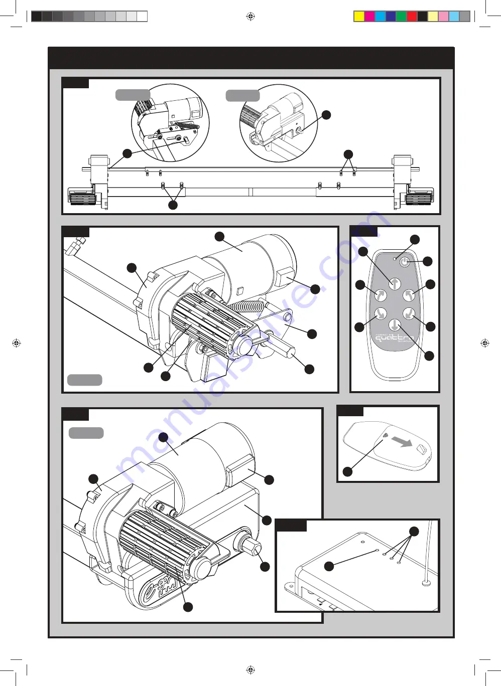
Parts Identification & Fitting Diagrams
Fig.1
Fig.3
A
B
C
D
E
F
G
H
Fig.4
Fig.6
Fig.5
EGO400
EGO130
Fig.2
PL CM manual AU 01-15.indd 3
14/1/15 10:43:39
Страница 1: ...User Manual For use with Model Numbers EGO130 EGO400 Ref CM UM 0115 Rev C AUS Caravan Movers PL CM manual AU 01 15 indd 1 14 1 15 10 43 37...
Страница 2: ...A 3 2 1 5 4 6 WEIG MAT DATE SIGNATURE NAME FINISH UNLESS OTHERWISE SPECIFIED DIMENSIONS ARE IN MILLIMETERS SURFACE FINISH TOLERANCES LINEAR ANGULAR Q A MFG APPV D CHK D DRAWN D E F C 1 2 3 4 B A 3 2...
Страница 3: ...rts Identification Fitting Diagrams Fig 1 Fig 3 A B C D E F G H A B C A Fig 4 Fig 6 A B Fig 5 A B C G A EGO400 D F EGO130 EGO130 Fig 2 A B C D E F G EGO400 PL CM manual AU 01 15 indd 3 14 1 15 10 43 3...
Страница 4: ...on CAUTION Do not exert undue pressure on winding spindle when rollers are fully disengaged When resistance is met STOP WINDING Failure to do this may result in mechanical damage Fig 7 A Fig 9 Fig 10...
Страница 5: ...A 10mm A 12 11 10 9 8 7 6 5 4 13 14 15 16 17 18 19 20 21 22 165mm min 85mm min 1800mm to 2500mm max Fig 18 Fig 16A Fig 18A L Profile U Profile Caravan Floor European Type Chassis Fig 14 EGO400 A 10mm...
Страница 6: ...Parts Identification Fitting Diagrams Fig 20 Caravan Front 1 2 3 4 1 2 CONTROL UNIT BATTERY Fig 19 PL CM manual AU 01 15 indd 6 14 1 15 10 43 41...
Страница 7: ...e cable to terminal 2 Motor 2 Positive cable to terminal 3 Motor 2 Negative cable to terminal 4 FRONT OF AXLE MOTORS Use the Front of Axle wiring when installing a two motor system Use the Front of Ax...
Страница 8: ...Motor Unit 2 4 four motor system 20 10 Cable Trunking P Clips 19 2mm 3 1 Main Cross Bar 21 10 Cable P Clips 10 4mm 4 1 Cross Actuation Centre Bar 22 4 Battery Terminal Connector 8mm 5 2 Cross Actuati...
Страница 9: ...lso suitable for most European type chassis and will not normally require the use of the chassis plates 37 and will instead fit straight onto the lip of an L profile or U profile chassis please refer...
Страница 10: ...s are in the DISENGAGED position Fig 8 or Fig 12 as the unit will not fit correctly otherwise Loosely assemble motor unit 1 motor unit 2 and main cross bar 3 see Fig 1 The nuts Fig 1B on the cross bar...
Страница 11: ...ase substitute these as appropriate Drill a 25 mm hole through the floor of the caravan approximately 150 mm centrally in front of the control unit 32 terminals Caution Take extra care to avoid any ch...
Страница 12: ...ing crimping pliers A secure and good quality connection on each cable is essential Finally connect the Battery Cables 14 15 to the Control Unit 32 Installation of your Purple Line Caravan Mover is no...
Страница 13: ...ply refit the tool onto one of the spindles and rotate away from the tyre Please note that you will feel a small amount of resistance initially as you disengage the cam from its locked position the sp...
Страница 14: ...aravan is responsible for controlling the caravan mover The control unit has three LED s Fig 6 and one recessed button Fig 6A Green LED This will illuminate when receiving the signal The LED will flas...
Страница 15: ...one motor going in one direction and the other going in the opposite direction This is ideal for single axle caravans You will not need to do anything with the electronics if you have installed a sin...
Страница 16: ...r other unauthorised people It is possible to position the caravan s hitch exactly over a stationery car s tow ball using the mover But please be very careful Use the button controls on the remote con...
Страница 17: ...electronics box Blue LED is on and Red LED is flashing twice slowly If empty recharge completely or renew caravan battery before taking any further action Advice on battery voltage Even though batteri...
Страница 18: ...e remote control and the caravan is not more than 5 metres If there is no signal between the remote control and control box the mover will not function at all even though the LED on the remote control...
Страница 19: ...e due to customer misuse or neglect This warranty is not offered for any type of trade or commercial usage The manufacturer does not take responsibility for any consequential loss whatsoever Upon insp...
Страница 20: ...ne Pty Ltd Photographs are for illustration purposes only Actual product may differ Purple Line reserve the right to change product specifications without prior notice PL CM manual AU 01 15 indd 13 14...