


RUPS824P
RACK POWER
7
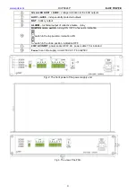
off – no DC voltage at the output of the switch mode PSU
RED LED:
on – failure
off – no failure
RED LED:
ON – too high temperature of the switch mode power supply
(>70°C)
OFF – standard temperature of the switch mode power supply
RED LED:
on – battery voltage <23V
off – battery voltage >23V
GREEN LED:
on – DC voltage in the AUX1…AUX8 output
off – no DC voltage in the AUX1…AUX8 output
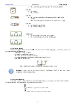
3.2. Technical output.
The power supply is fitted with the
ALARM
output of collective failure (relay type). A collective failure can
be triggered by the following events:
- 230V AC mains power failure
- Activation of the polymer fuse PTC
- Failure of the switch mode power supply
- Too high temperature of the switch mode power supply (>70
°C)
- Low battery voltage (<23V)
Fig. 4. Electrical diagram of the ALARM collective output of failure.
CAUTION!
In Fig.4 the set of contacts shows a potential-free status of the relay, which
corresponds to power supply failure.
3.3. Acoustic indication.
A collective failure is indicated by the piezoelectric indicator, 1 beep every second. The acoustic indication
can be turned off by changing the ON / OFF position of the switch .
switch in the up position, indication ON
switch in the down position, indication OFF


