background image

www.pulsar.pl   


EN54-7A28 


RED POWER


27 

The  connection  of  external  devices  to  the  EXT  IN  input  is  shown  in  the  electrical  diagram  below.  OC  

outputs (open collector) or  relay outputs can be used as the source of the signal.  


Fig. 12. Examples of connections. 


In  the  option  with  external  switch,  the  V EXT   jumper, which polarises  the  EXT  IN  input  circuit and 

is required in such configuration, must  be  on.   

The EXTi input has been adjusted to work with fuse modules generating a failure signal in case of a fuse 

fault in any of output sections (see section 6.7). To guarantee a correct cooperation between the fuse module and 
the EXTi input, the connections shall be made as presented in the diagram below and the V EXT jumper must be 
on. 


Fig. 13. Example of a connection with the fuse module EN54-LB8. 


6.6. Indication of the enclosure opening - TAMPER. 

 
The PSU is fitted with the microswitch tamper indicating enclosure opening.  
The  tamper  cable  is  not  connected  to  the  terminal  in  the  factory  settings.  In  order  to  activate  tamper, 

remove the jumper from tamper terminal (Fig. 2 [12]) and plug in the tamper cable. 

Each  opening  the  enclosure  will  generate  a  failure  signal  at  the  PSU  FLT  and  ALARM  technical  outputs 

and will save the event in the internal memory of the PSU. 


Содержание RED POWER EN54-7A28

Страница 1: ...EN54 7A28 v 1 0 EN54 27 6V 7A 2x28Ah power supply for fire alarm systems EN Edition 1 from 28 11 2013 Supersedes the edition LED Version ...

Страница 2: ... failure codes and information messages 17 6 3 PSU CONFIGURATION 19 6 3 1 Performing battery test tSt 20 6 3 2 EXTo output ON OFF Eto 21 6 3 3 Setting the delay time for EPS output EPS 21 6 3 4 Acoustic indication ON OFF bUZ 22 6 3 5 LED Display Dimmer dIS 23 6 3 6 Setting the communication address Adr applies to cooperation with PowerSecurity 24 6 3 7 Setting the transmission speed trS applies to...

Страница 3: ...31 7 7 BATTERY TEMPERATURE MEASUREMENT 31 7 8 STANDBY TIME 31 8 REMOTE MONITORING OPTIONS WI FI ETHERNET RS485 USB 32 8 1 COMMUNICATION VIA THE USB TTL INTERFACE 32 8 2 ETHERNET NETWORK COMMUNICATION 32 8 3 THE WI FI WIRELESS COMMUNICATION 33 8 4 RS485 NETWORK COMMUNICATION 34 8 5 POWERSECURITY PROGRAM 35 9 TECHNICAL PARAMETERS 36 Table 12 Electrical parameters 36 Table 13 Mechanical parameters 37...

Страница 4: ...nt SERIAL communication port with implemented MODBUS RTU protocol free program PowerSecurity to monitor the performance of the PSU remote monitoring options WiFi Ethernet RS485 USB remote battery test additional modules required cooperation with optional EN54 LB4 or EN54 LB8 fuse modules optical indication of PSU overload OVL acoustic indication of failure adjustable delay for 230V AC power loss i...

Страница 5: ...al CD Red mounting spacers 4 pieces Red metal mounting brackets for hanging the power supply 4 pieces M8x16 mounting screws 4 pieces PG9 cable glands 4 pieces PG11 cable glands 4 pieces Battery serial connection cable Keys to lock the power supply 2 pieces Cable tie 190x4 8 12 pieces ...

Страница 6: ... YES YES Low battery indication YES YES Deep discharge battery protection YES YES Protection against short circuit of the battery terminals YES YES Battery fuse failure indication YES YES Charging circuit failure indication YES YES Low output voltage indication YES YES High output voltage indication YES YES Indication of power supply failure YES YES Overvoltage protection YES YES Short circuit pro...

Страница 7: ... Output current Imax b 7A In case of power loss the PSU switches to battery power providing uninterruptible power supply The PSU is enclosed in a metal casing RAL 3001 red with battery housing for two 28Ah 12V batteries The PSU works with maintenance free lead acid batteries made with AGM technology or gel technology 4 2 Block diagram The PSU has been manufactured based on a high efficiency system...

Страница 8: ...t voltage AUX2 AUX2 output voltage OVL PSU overload APS battery failure PSU PSU failure ALARM collective failure EXTi EXTi input status EXTo EXTo relay output status LB battery charging 11 Terminals AC AC power input EPS FLT technical output of AC power failure indication open AC power failure closed AC power O K PSU FLT technical output of PSU failure indication open failure closed PSU operation ...

Страница 9: ...2 Components of the PCB of the EMC filter Fig 3 Element nr Opis FMAINS fuse in the power supply circuit 230V T6 3A 250V L N power supply connector 230V AC PE protective connector Connector for connecting the PSU Fig 3 The view of the EMC filter ...

Страница 10: ... module INTR INTE INTW 5 Place to install the EN54 LB4 or EN54 LB8 fuse module 6 TAMPER microswitch contacts of antisabotage protection NC 7 EMC filter module see Table 2 Fig 3 8 2x28Ah batteries 9 Embossing for cable gland 10 Embossing for cable gland WiFi antenna or cable communication interface 11 Embossings for concealed wires 12 Lock 13 Battery connectors positive BAT red negative BAT black F...

Страница 11: ... free and convectional air flow through ventilating holes of the casing As the PSU performs a periodic battery test measuring the resistance of connections special attention should be paid to the proper connection of the cables to the batteries Installation cables should be firmly connected to the battery side terminals and to the power supply connector The side walls of the housing include the em...

Страница 12: ...f PSU failure APS FLT technical output of the battery failure EXTi input of collective failure 5 Install the batteries in a designated area of the enclosure see Fig 4 Connect the batteries with the PSU paying special attention to the correct polarity Batteries must be connected in series using the special cable included Attach the temperature sensor to any of the batteries with mounting tape inclu...

Страница 13: ... panel Description Additional information moves the pointer on the screen next screen selection selection approval red LED indicating 230V AC voltage red LED indicating exceeding the Imax a current or power supply overload section 6 9 6 10 red LED indicating PSU failure red LED indicating battery failure red LED ALARM indicating collective failure section 6 2 3 green LED AUX1 indicating power at t...

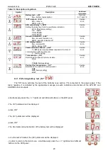
Страница 14: ...7 The description of display symbols Symbol Description Additional information AUX1 output voltage V Factory setting 27 6V 20 C AUX2 output voltage V Factory setting 27 6V 20 C Total current of the receivers A Io I AUX1 IAUX2 Resistance of the battery circuit Ω Section 7 6 Battery temperature C Section 7 7 Mains supply voltage V 230V AC mains supply voltage indication Failure history Section 6 2 6...

Страница 15: ...power supply unit will indicate a failure The measurement result is displayed with a resolution of 0 01 ohm 6 2 4 Battery temperature indicator t C Battery voltage indicator displays the measured temperature of the batteries The temperature is used by the automatic control system for compensation of the battery charging voltage The measurement result is displayed with a resolution of 1 C 6 2 5 230...

Страница 16: ...taneously indicate several failures Thanks to this solution codes of all failures and their priority can be previewed in the FLc menu In the FLc menu each press of the OK button on the panel displays the next error code that caused the failure If there are multiple failures at the same time pressing the OK button will display the next code The display order of failures is arranged by priority of i...

Страница 17: ...se failure AUX1 fuse Blown FAUX1 fuse F02 AUX2 fuse PSU FLT ALARM Blown FAUX2 fuse F03 BAT fuse APS FLT ALARM Blown FBAT fuse Short circuit in the battery circuit Short circuit in the AUX output circuit F04 Overloaded output PSU FLT ALARM PSU overload Section 6 9 F05 Undercharged battery APS FLT ALARM Spent batteries Undercharged batteries Section 7 High AUX1 voltage F06 High AUX2 voltage PSU FLT ...

Страница 18: ...95V AC Section 6 2 5 F21 Enclosure opening PSU FLT ALARM Section 6 6 F50 F54 Internal damage of the PSU PSU FLT ALARM service codes F60 No communication PSU FLT ALARM no communication with LCD panel F61 F64 LCD damage PSU FLT ALARM service codes F65 Access unlocked passwords unlocked Table 9 List of PSU message codes Message code Description I00 Running the PSU I01 AC power restored AUX1 fuse repl...

Страница 19: ...uration The PSU is equipped with a configuration menu that allows to configure the settings by changing or the activation of some of its parameters The figure illustrating the configuration menu structure is shown below Fig 9 The PSU configuration menu ...

Страница 20: ...mission trS Determines the speed of communication 9 6k 115 2k factory setting Section 6 3 7 Parity of the transmission trP Determines the method of communication 8N2 8E1 factory setting 8O1 Section 6 3 8 6 3 1 Performing battery test tSt The tSt menu activates the test of the batteries see section 7 5 connected to the power supply If the test is negative it is indicated by the appropriate message ...

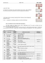
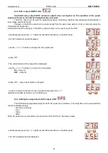
Страница 21: ... leftmost buttons on the LED panel the tSt parameter will be displayed use the or buttons to display the Eto parameter press OK The current status of the relay will be displayed use the or buttons to in order to set the status On relay on OFF relay off press OK relay output status is changed in order to return to the main menu simultaneously press the rightmost and leftmost buttons on the LED pane...

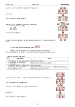
Страница 22: ...dicated acoustically The frequency and number of signals depend on the type of event Table 11 Acoustic indication No Description Event 1 1 signal every 10s battery mode 230V AC power failure 2 1 signal every 10s mains operation Battery failure undercharged batteries 3 2 signals every 10s battery mode Low battery level 4 Fast signals battery mode The PSU will be disconnected because of the battery ...

Страница 23: ...ay if no buttons are pressed within 5 minutes If the display is in the blackout mode pressing any button will reactivate the display simultaneously press the rightmost and leftmost buttons on the LED panel the tSt parameter will be displayed use the or buttons to display the dIS parameter press OK The current status will be displayed use the or buttons in order to set the status On dimmer on OFF d...

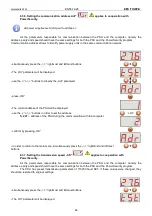
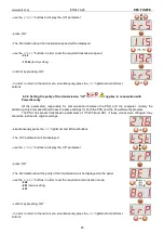
Страница 24: ...ter press OK The current address of the PSU will be displayed use the or buttons in order to set the address 1 247 address of the PSU during the communication with the computer confirm by pressing OK in order to return to the main menu simultaneously press the rightmost and leftmost buttons 6 3 7 Setting the transmission speed trS applies to cooperation with PowerSecurity All the parameters respon...

Страница 25: ...the PSU and the computer namely the address parity and speed should have the same settings for both the PSU and the PowerSecurity program The PSU has preset transmission parameters of 115200 baud 8E1 if these values were changed they should be restored to original settings simultaneously press the rightmost and leftmost buttons The tSt parameter will be displayed use the or buttons to display the ...

Страница 26: ...l status during correct operation the output is closed In case of PSU failure it will switch into the open position Failure can be triggered by the following events UAUX1 AUX2 output voltage below 26V UAUX1 AUX2 output voltage over 29 2V battery charging circuit failure blown FAUX1 or FAUX2 fuse exceeding the rated current of the PSU activation of overvoltage protection OVP mains supply voltage ov...

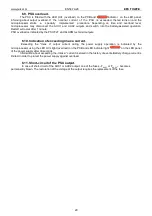
Страница 27: ...sections see section 6 7 To guarantee a correct cooperation between the fuse module and the EXTi input the connections shall be made as presented in the diagram below and the V EXT jumper must be on Fig 13 Example of a connection with the fuse module EN54 LB8 6 6 Indication of the enclosure opening TAMPER The PSU is fitted with the microswitch tamper indicating enclosure opening The tamper cable i...

Страница 28: ...er supply current consumption used for the calculation of standby time see section 7 8 should be taken into account Depending on the version fuse module allows to connect 4 or 8 receivers to the PSU Output state is indicated by green LEDs Blown fuse is indicated as follows corresponding LED turns off L1 for AUX1 etc red LED on PSU technical output on Hi Z state switching PSU relay output into volt...

Страница 29: ... PSU FLT and ALARM technical outputs 6 10 Indication of exceeding Imax a current Exceeding the Imax a output current during the power supply operation is indicated by the microprocessor using the LED OVL light overload on the PCB and LED indicator light on the LED panel of the power supply after 30 seconds Information about exceeding the Imax a current is stored in the history of events Battery ch...

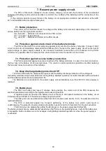
Страница 30: ...t connection the FBAT fuse in the battery circuit becomes blown The return to normal operation is possible only after replacing the fuse and correct connection of the batteries 7 4 Deep discharge battery protection UVP The PSU is fitted with the disconnection system and the battery discharge indication If the voltage at the battery terminals drops below 20V 0 2V during battery assisted operation a...

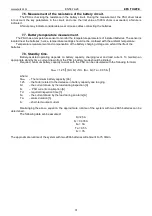
Страница 31: ... batteries 7 8 Standby time Battery assisted operating depends on battery capacity charging level and load current To maintain an appropriate standby time current drawn from the PSU in battery mode should be limited Required minimum battery capacity to work with the PSU can be calculated with the following formula QAKU 1 25 Id Iz Td Ia Iz Ta 0 05 Ic where QAKU The minimum battery capacity Ah 1 25 ...

Страница 32: ...ower supply unit power supply current consumption used for the calculation of standby time should be taken into account see section 7 8 8 1 Communication via the USB TTL interface The easiest way of communication between the PSU and the computer is provided by the USB TTL INTU interface This interface allows direct connection between the computer and the PSU and is recognizable by the operating sy...

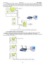
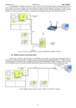
Страница 33: ... against adverse environmental conditions Fig 17 Ethernet network communication using the RS485 INTRE interface 8 3 The Wi Fi wireless communication The Wi Fi wireless communication can be implemented on the basis of additional interfaces WI Fi INTW and RS485 WiFi operating within 2 4GHz frequency band according to the IEEE 802 11 bgn standard The WiFi INTW interface shall be mounted in a selected...

Страница 34: ...st adverse environmental conditions Fig 19 The Wi Fi communication using the RS485 WIFI INTRW interface 8 4 RS485 network communication Another type of network communication is the RS485 communication using two wire transmission path To achieve this kind of data exchange the PSU should be equipped with the additional RS485 TTL INTR interface converting data from the PSU into the RS485 standard and...

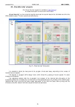
Страница 35: ...of the program into smaller areas depending on the number of monitored power supplies The program is equipped with manager mode which allows the grouping of power supplies for easier analysis and orientation The application enables both the visualization and analysis of the received data Exceeding of the acceptable parameters is indicated by red illumination of the appropriate area or by blinking ...

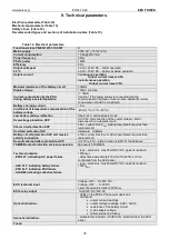
Страница 36: ...ion OVP U 30 5V disconnection of the output voltage AUX disconnection automatic return Short circuit protection SCP F8A current limit FAUX melting fuse failure requires fuse replacement Overload protection OLP Hardware Software Battery circuit protection SCP and reverse polarity connection F10A current limit FBAT melting fuse failure requires fuse replacement Deep discharge battery protection UVP ...

Страница 37: ...uts Ф0 51 2 AWG 24 12 Battery outputs BAT Ф6 M6 0 2 5 Cable glands PG9 cable diameter Ф4 8mm PG11 cable diameter Ф5 10mm Notes The enclosure does not adjoin the mounting surface so that cables can be led Convection cooling Table 14 Safety of use Protection class PN EN 60950 1 2007 I first Protection grade PN EN 60529 2003 IP44 Insulation electrical strength between input network circuit and the ou...

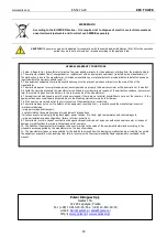
Страница 38: ...ir if it is used in dusty conditions In case of fuse replacement use only compatible replacement parts Technical inspections should be carried out not less frequently than once per year During the inspection check the batteries and run the battery test 4 weeks after installation re tighten all threaded connections see Fig 2 11 and Fig 3 2 CAUTION According to the recommendations of the CNBOP and V...

Страница 39: ...www pulsar pl EN54 7A28 RED POWER 39 ...

Страница 40: ...ged to provide warranty repairs at the earliest convenience however not later that within 14 days from the delivery to the service centre of the manufacturer 6 The repair period mentioned in point 5 may be prolonged if there are no technical possibilities to carry out the repairs or if the equipment has been conditionally accepted due to the breaking warranty terms by the claimant 7 All the servic...

Отзывы: