Pulsar GREEN POWER CCTV BNC04124 Скачать руководство пользователя страница 7

www.pulsar.pl


BNC04124 


G

REEN POWER CCTV BNC


RED LED: 


on – DC voltage at the output of the switch mode PSU  


off – no DC voltage at the output of the switch mode PSU 

 
RED LED: 


on – fuse failure at one of the AUX1…AUX4 outputs 


off – no failure 


GREEN LED: 


on – DC voltage at the AUX1…AUX4 output 


off – no DC voltage at the AUX1…AUX4 output 


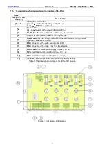
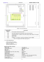
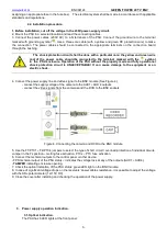
Additionally, the PSU is fitted with LED lights inside the enclosure – see Figure 2 and 3: 
L

IN

 green LED (Figure 2, component 1) indicates DC voltage at the BNC module input. During normal operation 

(DC supply) the LED is permanently illuminated. No DC no DC voltage at the module input is indicated by turning 
off the L

IN 

LED.  

L

FPS

 red LED (Figure 2, component 11 is not illuminated during normal operation (no failure). In case of activation 

of the short circuit / overload protection at any output, the LED is permanently illuminated.  
L1 ÷ L4 green LEDs (Figure 2, component 5) indicate voltage at the individual outputs of the module (L1 for AUX 
1 etc.). Activation of the short circuit / overload protection of a given circuit is indicated by turning off one of the Lx 
LEDs.  
 

3.2. Technical outputs. 


The PSU has the following indication outputs: 
 

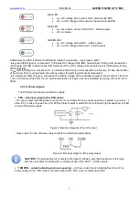
  FPS – technical output of the PSU status:  

-  OC  type  output  indicating  failure  (short-circuit,  overload).  During  normal  operation,  shorted  to  ground  –  L 
state (0V). In case of power loss, the FPS technical output is switched into hi-Z state (high impedance) at least 
at one of the AUX outputs.  


Figure 5. Electrical diagram of the OC output. 


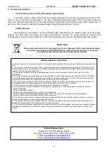
- relay output. In case of failure, relay contacts are switched automatically. 


Figure 6. Electrical diagram of the relay output 

 
CAUTION! The arrangement of contacts at the figure 6 shows a potential-free status of the relay, 
which is equivalent to a state with no voltage at any of the AUX1 ÷ AUX4 outputs. 


  TAMPER – output indicating enclosure opening: - volt free contact input indicating the status of the 

power supply doors, PSU closed: contacts closed (NC), PSU open: contacts open (NO). 


Содержание GREEN POWER CCTV BNC04124

Страница 1: ...BNC04124 v 1 0 BNC 12V 4x1A Switch mode power supply unit for CCTV EN Edition 1 from 26 11 2013 Supersedes the edition BNC GREEN POWER CCTV ...

Страница 2: ...puts 4 Service and operation 4 1 Overload or short circuit of the power supply output 4 2 Maintenance 1 Technical description 1 1 General description The PSU BNC04124 is intended for uninterrupted supply of CCTV systems requiring stabilized voltage of 12V DC The output voltage can be adjusted with a potentiometer between 12V and 15V DC The power supply unit enables transmitting power and video usi...

Страница 3: ...cuits 4 Jumper to select melting fuse or PTC polymer fuse 5 Green LED L1 L4 voltage indication at the AUX outputs during normal operation these LEDs are on 6 BNC connector of the video output to the DVR 7 BNC connector of the video input from the cameras 8 AUX1 AUX4 camera power supply outputs 12 15V 9 FPS technical output indicating failure OC type 10 FPS technical output indicating failure relay...

Страница 4: ... Figure 3 1 4 Technical parameters electrical parameters Table 3 mechanical parameters Table 4 safety of use Table 5 operation parameters Table 6 Electrical parameters Table 3 Mains supply 176 264V AC Current consumption 0 6A 230V AC max PSU s power 48W max Efficiency 80 Output voltage 12V DC The adjustment range of the output voltage 12 15V DC Output current 4x 1 A Ripple voltage 100 mV p p max S...

Страница 5: ...E protection circuit O P FG 3000 V AC min 1500 V AC min 500 V AC min Insulation resistance between input circuit and output or protection circuit 100 MΩ 500V DC Operation parameters Table 6 Operating temperature 10ºC 40ºC see Figure1 Storing temperature 20ºC 60ºC Relative humidity 20 90 no condensation Vibrations during operation unacceptable Surges during operation unacceptable Direct insolation ...

Страница 6: ...ircuit is UNACCEPTABLE It can cause damage to the equipment or an electric shock 4 Connect the power supply line and video signal to the BNC module See Figure 4 connect the supply voltage of the camera to the AUX1 AUX 4 outputs connect the video signals from the cameras and the DVR to the BNC sockets Figure 4 Connecting the camera and DVR to the BNC module 5 Use the F1 PTC1 F4 PTC4 jumpers to sele...

Страница 7: ...re 2 component 5 indicate voltage at the individual outputs of the module L1 for AUX 1 etc Activation of the short circuit overload protection of a given circuit is indicated by turning off one of the Lx LEDs 3 2 Technical outputs The PSU has the following indication outputs FPS technical output of the PSU status OC type output indicating failure short circuit overload During normal operation shor...

Страница 8: ...rer 4 The warranty applies to complete equipment accompanied by a properly filled warranty claim with a description of the defect 5 Should the claim be accepted the manufacturer is obliged to provide warranty repairs at the earliest convenience however not later that within 14 days from the delivery to the service centre of the manufacturer 6 The repair period mentioned in point 5 may be prolonged...

Отзывы: