

www.pulsar.pl
BNC04124
G
REEN POWER CCTV BNC
3
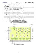
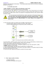
1.3. The description of components and connectors of the PSU.
Table 1.
Component No.
[Figure 2]
Description
[1], [11]
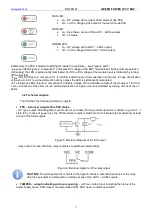
LED optical indication:
green L
IN
– indication of voltage at the IN input
red L
FPS
–FPS failure indication
[2]
Connector:
IN – power supply of the module (factory setting)
[3]
F1, F2, F3, F4 fuses in the AUX1 ÷ AUX4 (+), F1A circuits
[4]
Jumper to select melting fuse or PTC polymer fuse
[5]
Green LED L1 ÷ L4 – voltage indication at the AUX outputs (during normal
operation, these LEDs are on)
[6]
BNC connector of the video output to the DVR
[7]
BNC connector of the video input from the cameras
[8]
AUX1÷AUX4 – camera power supply outputs (12÷15V)
[9]
FPS – technical output indicating failure – OC type
[10]
FPS – technical output indicating failure – relay type
[12]
Optional, external optical indication connector (factory setting)
Table 1. The description of components of the BNC module.
Figure 2. Components arrangement.