PSH MOTOPLAT VC-11R Скачать руководство пользователя страница 2

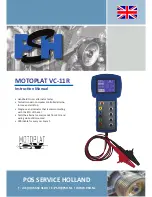
Motoplat VC-11R Instruction Manual

IMPORTANT INFORMATION 

Safety warning

Electrical devices should be installed and operated in such a way that all applicable safety requirements 

are met. It is your responsibility as an installer to ensure that you identify the relevant safety standards and 

comply with them. Failure to do so may result in damage to equipment and personal injury. In particular, 

you should study the contents of this guide carefully before installing or operating the equipment.

People who start using this product should review carefully this instruction manual, or have had a training 

from a qualified person.

The use of electrical equipment is entirely at your own risk and Pos Service Holland is under no circum

-

stances responsible for any incidental, consequential or special damages of any kind whatsoever, 

including but not limited to lost profits arising from or in any way connected with the use of the automated 

test equipment or this manual.

Since this tester operates in conjunction with car electronics, you should also be aware of car electronics 

and automotive technology and the associated safety requirements.

- Pos Service Holland -

Pos Service Holland  


Page 2  

Environment

The tester should be installed in a weather protected area where heat, humidity or any other climate 


situation can not damage the tester.

Содержание MOTOPLAT VC-11R

Страница 1: ...truction Manual Handheld On car alternator tester Tests all modern computer controlled alterna tors even start stop Diagnose an alternator that is communicating with the ECU of the car Tests the alter...

Страница 2: ...tion manual or have had a training from a qualified person The use of electrical equipment is entirely at your own risk and Pos Service Holland is under no circum stances responsible for any incidenta...

Страница 3: ...11R tester to power source 5 2 1 Connect the Motoplat VC 11R tester to the alternator COM 6 2 2 Connect the Motoplat VC 11R tester to the alternator Ford Opel 6 3 Instructions 3 0 Plug Button explanat...

Страница 4: ...Landrover GM Scania PD Drive Mazda RLO Toyota sense C Hyundai Kia Nissan from 2005 Honda DFM Positive Negative 24 Volt Mercedes Benz Volkswagen Audi PSA Honda Toyota After selecting the right mode th...

Страница 5: ...R works in combination with the car electronics That is why it is necessary to connect the VC 11R to the car battery by using the cables B and GND Attach the red B cable to the 12V socket of the car b...

Страница 6: ...plug connection by using the red input cable When the VC 11R tester is connected correctly it will turn on automatically 2 2 Connect the Motoplat VC 11R tester to the alternator Ford Opel Disconnect...

Страница 7: ...put signal DFM Pos Neg 24v DFM Measurement input signal DFM Pos Neg 24v Output Output to the alternator Input Input to car ECU OFF No voltage setpoint 12 5V Voltage set point button 13 5V Voltage set...

Страница 8: ...Test System COM LIN 1 3 H Baud 9600 Connection A COM output Input A 3 1 Field duty cycle Increase as high as possible by activating the car accessories 2 Voltage output Pass when it s close to the se...

Страница 9: ...em COM LIN 2 1 H Baud 19200 Connection A COM output Input A 3 1 Field duty cycle Increase as high as possible by activating the car accessories 2 Voltage output Pass when it s close to the set voltage...

Страница 10: ...point Voltage can be changed by pressing buttons 12 5V 13 5V 15 5V OFF With low load only 4 Pass Error Pass If you can change VSP No message Error Mechanical Electrical Temperature VSP doesn t change...

Страница 11: ...est System COM BSS_2 Connection A COM output Input A 3 1 Field duty cycle Increase as high as possible by activating the car accessories 2 Voltage output Pass when it s close to the set voltage 0 4V d...

Страница 12: ...est System COM BSS_3 Connection A COM output Input A 3 1 Field duty cycle Increase as high as possible by activating the car accessories 2 Voltage output Pass when it s close to the set voltage 0 4V d...

Страница 13: ...e mode button select Generator Test Ford and press OFF System PWM Focus Mondeo Connection A PWM DFM Output Input A 3 1 Field duty cycle Increase as high as possible by activating the car accessories 2...

Страница 14: ...e mode button select Generator Test Opel and press OFF System PWM Opel GM Connection A PWM DFM Output Input A 3 1 Field duty cycle Increase as high as possible by activating the car accessories 2 Volt...

Страница 15: ...all function in the same way Function About the DFM connection there is a positive and negative measurement and both work with a block pulse When the alternator load increases the block pulse dependi...

Страница 16: ...ntact Information Pos Service Holland BV Stichtse Kade 47c 1244NV s Graveland Holland Telephone 31 0 35 656 3180 Fax 31 0 35 656 0409 Email psh psh nl Website www psh nl Technical support Contact pers...

Отзывы: