background image


WIL-11050-E-05


Wilden

®


13 

Suggested Installation, Operation, Maintenance and Troubleshooting 
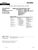
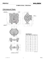
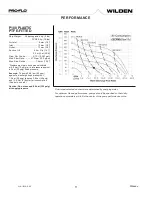
 

The Pro-Flo

®

 model 

P100 Advanced

™ plastic has a 13 mm (1/2") inlet 

and 13 mm (1/2") outlet and is designed for flows to 58.7 lpm (15.5 gpm). 
The 

P100 Advanced

™ plastic pump is manufactured with wetted parts 

of pure, unpigmented Polypropylene or PVDF. The 

P100 Advanced

™ 

plastic pump is constructed with a glass fiber filled PP center section.  
A variety of diaphragms and o-rings are available to satisfy temperature, 

chemical compatibility, abrasion, and flex concerns. 

The suction pipe size should be at least 13 mm (1/2”) diameter or larger 

if highly viscous material is being pumped. The suction hose must be 
non-collapsible, reinforced type as the 

P100 Advanced

™ plastic pump 

is capable of pulling a high vacuum. Discharge piping should be at least 

13 mm (1/2”); larger diameter can be used to r

educe friction losses. It is 

critical that all fittings and connections are airtight or a reduction or loss 
of pump suction capability will result. 


CAUTION: 

All fittings and connections must be airtight. 

Otherwise, pump suction capability will be reduced or lost.


Months of careful planning, study and selection efforts can result in 
unsatisfactory pump performance if installation details are left to 
chance. You can avoid premature failure and long-term dissatisfaction 
by exercising reasonable care throughout the installation process

.


Location


Noise, safety and other logistical factors usually dictate where 
equipment will be situated on the production floor. Multiple installations 

with conflicting requirements can result in congestion of utility areas, 
leaving few choices for additional pumps. 
Within the framework of these and other existing conditions, every 
pump should be located in such a way that several key factors are 
balanced against each other to maximum advantage.: 

 Access: 

First of all, the location should be accessible. If 

it’s easy 

to reach the pump, maintenance personnel will have an easier 
time carrying out routine inspections and adjustments. Should 
major repairs become necessary, ease of access can play a key 

role in speeding the repair process and reducing total downtime. 

 Air Supply: 

Every pump location should have an air line large 

enough to supply the volume of air necessary to achieve the 
desired pumping rate. Use air pressure up to a maximum of 8.6 
bar (125 psig) depending on pumping requirements. 

For best results, the pumps should use a 5μ (micron) air

 filter, 

needle valve and regulator. The use of an air filter before the 
pump will ensure that the majority of any pipeline contaminants 
will be eliminated. 

• Solenoid Operation: 

When operation is controlled by a solenoid 

valve in the air line, three-way valves should be used. This valve 

allows trapped air between the valve and the pump to bleed off 
which improves pump performance. Pumping volume can be 
estimated by counting the number of strokes per minute and then 
multiplying the figure by the displacement per stroke. 

• Muffler: 

Sound levels are reduced below OSHA specifications using 

the standard Wilden muffler. Other mufflers can be used to further 
reduce sound levels, but they usually reduce pump performance. 

• 

Elevation: 

Selecting a site that is well within the pump’s


dynamic-lift capability will assure that loss-of-prime issues will 

be eliminated. In addition, pump efficiency can be adversely 
affected if proper attention is not given to site location. 

• Piping: 

Final determination of the pump site should not be 

made until the piping challenges of each possible location have 
been evaluated. The impact of current and future installations 
should be considered ahead of time to make sure that 
inadvertent restrictions are not created for any remaining sites. 

The best choice possible will be a site involving the shortest and 
straightest hook-up of suction and discharge piping. Unnecessary 
elbows, bends and fittings should be avoided. Pipe sizes should be 
selected to keep friction losses within practical limits. All piping should 
be supported independently of the pump. In addition, the piping 
should be aligned to avoid placing stress on the pump fittings. 

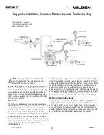
Flexible hose can be installed to aid in absorbing the forces created 
by the natural reciprocating action of the pump. If the pump is to be 
bolted down to a solid location, a mounting pad placed between the 
pump and the foundation will assist in minimizing pump vibration. 
Flexible connections between the pump and rigid piping will also 
assist in minimizing pump vibration. If quick-closing valves are 

installed at any point in the discharge system, or if pulsation within a 
system becomes a problem, a surge suppressor (SD Equalizer

®

should be installed to protect the pump, piping and gauges from 
surges and water hammer. 

The 

P100 Advanced™ 

plastic Pro-Flo

®

 equipped pump can be 

installed in submersible applications only when both the wetted and 
non-wetted portions are compatible with the material being pumped. 

If the pump is to be used in a submersible application, a hose should 
be attached to the air and pilot spool exhaust ports of the pump. 
These should then be piped above the liquid level. The exhaust area 
for the pilot spool is designed to be tapped for a 1/8" NPT fitting. 

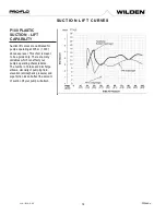
If the pump is to be used in a self-priming application, make sure 
that all connections are airtight and that the suction lift is within 

the model’s ability. 


NOTE:

 Materials of construction and elastomer material have 

an effect on suction-lift parameters. Please refer to the 
performance section for specifics. 

When pumps are installed in applications involving flooded suction or 
suction-head pressures, a gate valve should be installed in the 

suction line to permit closing of the line for pump service. 

Pumps in service with a positive suction head are most efficient when 
inlet pressure is limited to 0.5

0.7 bar (7

10 psig). Premature 

diaphragm failure may occur if positive suction is 0.7 bar (10 psig) 
and higher. 

CAUTION:

 The model P100 Advanced

™ plastic will pass

 1.6 

mm (1/16") solids. whenever the possibility exists that larger 

solid objects may be sucked into the pump, a strainer should 
be used on the suction line. 

CAUTION:

 Do not exceed 8.6 bar (125 psig) air  

supply pressure. 


Section 6 

Содержание WILDEN P100 Advanced Plastic

Страница 1: ...EOM ENGINEERING OPERATION MAINTENANCE P100 Bolted Plastic Pump WIL 11050 E 05 Where InnovationFlows ...

Страница 2: ...al Ported 8 Section 5 Performance 10 P100 Advanced Plastic Rubber Fitted 10 P100 Advanced Plastic TPE Fitted 10 P100 Advanced Plastic PTFE Fitted 11 Suction Lift Curves 12 Section 6 Suggested Installation Operation 13 Maintenance and Troubleshooting Section 7 Disassembly Reassembly 16 Pump Disassembly 16 Air Valve Center Section Disassembly 19 Reassembly Hints Tips 21 Section 8 Exploded View and P...

Страница 3: ...lifornia LLC Wil Flex is a trademark of PSG California LLC Saniflex is a trademark of PSG California LLC All trademarks names logos and service marks collectively trademarks in this document are registered and unregistered trademarks of their respective owners Nothing contained in this document should be construed as granting any license or right to use any trademark without the prior written perm...

Страница 4: ... handling flammable fluids or whenever discharge of static electricity is a hazard CAUTION Do not exceed 8 6 bar 125 psig air supply pressure CAUTION Advanced series plastic pumps are made with plastic that is not UV stabilized Direct sunlight for prolonged periods can cause deterioration of plastics CAUTION Before any maintenance or repair is attempted the compressed air line to the pump should b...

Страница 5: ...UNA N PU POLYURETHANE Brown TV PTFE ENCAP FKM WF WIL FLEX Santoprene VT FKM NOTE Most Elastomeric materials use colored dots for identification NOTE Not all models are available with all material options Hytrel is a registered trademark of DuPont Dow Elastomers P100 ADVANCED PLASTIC 13 mm 1 2 Pump Maximum Flow Rate 58 7 LPM 15 5 GPM Section 2 W I L D E N P U M P D E S I G N A T I O N S Y S T E M S...

Страница 6: ...and manifold of the pump These same hydraulic forces lift the discharge valve ball off its seat while the opposite discharge valve ball is forced onto its seat forcing fluid to flow through the pump discharge The movement of diaphragm A toward the center section of the pump creates a vacuum within liquid chamber A Atmospheric pressure forces fluid into the inlet manifold of the pump The inlet valv...

Страница 7: ...SIONS ITEM METRIC mm STANDARD inch A 234 9 2 B 51 2 0 C 170 6 7 D 254 10 0 E 279 11 0 F 81 3 2 G 25 1 0 H 114 4 5 J 201 7 9 K 170 6 7 L 145 5 7 M 114 4 5 N 81 3 6 P 102 4 0 R 8 0 3 S 188 7 4 T 155 6 1 U 130 5 1 V 140 5 5 LW0347 REV B DIMENSIONAL DRAWING ...

Страница 8: ...d DIMENSIONS ITEM METRIC mm STANDARD inch A 234 9 2 B 51 2 0 C 170 6 7 D 254 10 0 E 279 11 0 F 81 3 2 G 25 1 0 H 114 4 5 J 201 7 9 K 170 6 7 L 145 5 7 M 114 4 5 N 81 3 6 P 102 4 0 R 8 0 3 S 188 7 4 T 155 6 1 U 130 5 1 V 140 5 5 LW0472 REV A DIMENSIONAL DRAWING ...

Страница 9: ...ed DIMENSIONS ITEM METRIC mm STANDARD inch A 234 9 2 B 51 2 0 C 170 6 7 D 254 10 0 E 279 11 0 F 81 3 2 G 25 1 0 H 114 4 5 J 201 7 9 K 170 6 7 L 145 5 7 M 114 4 5 N 81 3 6 P 102 4 0 R 8 0 3 S 188 7 4 T 155 6 1 U 130 5 1 V 140 5 5 LW0473 REV A DIMENSIONAL DRAWING ...

Страница 10: ...ps should be specified so that daily operation parameters will fall in the center of the pump performance curve P100 PLASTIC TPE FITTED Ship Weight Polypropylene 4 kg 8 lbs PVDF 5 kg 10 lbs Air Inlet 6 mm 1 4 Inlet 13 mm 1 2 Outlet 13 mm 1 2 Suction Lift 5 5 m Dry 17 0 8 7 m Wet 28 4 Disp Per Stroke1 0 11 l 0 029 gal Max Flow Rate 58 7 lpm 15 5 gpm Max Size Solids 1 6 mm 1 16 1 Displacement per st...

Страница 11: ...ke was calculated at 4 8 bar 70 psig air inlet pressure against a 2 bar 30 psig head pressure Example To pump 20 8 lpm 5 5 gpm against a discharge head pressure of 1 4 bar 20 psig requires 2 8 bar 40 psig and 13 6 Nm3 h 8 scfm air consumption See dot on chart Caution Do not exceed 8 6 bar 125 psig air supply pressure Flow rates indicated on chart were determined by pumping water For optimum life a...

Страница 12: ...ng at 305 m 1 000 above sea level This chart is meant to be a guide only There are many variables which can affect your pump s operating characteristics The number of intake and discharge elbows viscosity of pumping fluid elevation atmospheric pressure and pipe friction loss all affect the amount of suction lift your pump will attain ...

Страница 13: ... are reduced below OSHA specifications using the standard Wilden muffler Other mufflers can be used to further reduce sound levels but they usually reduce pump performance Elevation Selecting a site that is well within the pump s dynamic lift capability will assure that loss of prime issues will be eliminated In addition pump efficiency can be adversely affected if proper attention is not given to...

Страница 14: ... the volume and or pressure of the air supply to the pump An air regulator is used to regulate air pressure A needle valve is used to regulate volume Pump discharge rate can also be controlled by throttling the pump discharge by partially closing a valve in the discharge line of the pump This action increases friction loss which reduces flow rate See Section 5 This is useful when the need exists t...

Страница 15: ...Pump runs but little or no product flows 1 Check for pump cavitation slow pump speed down to allow thick material to flow into liquid chambers 2 Verify that vacuum required to lift liquid is not greater than the vapor pressure of the material being pumped cavitation 3 Verify that vacuum required to lift liquid is not greater than the vapor pressure of the material being pumped cavitation 4 Checkfo...

Страница 16: ...charge and air lines Drain the pump by turning it upside down and allowing any fluid to flow into a suitable container Be aware of any hazardous effects of contact with your process fluid NOTE The model used for these instructions incorporates PTFE diaphragms and balls Models with rubber diaphragms and balls are the same except where noted NOTE Replace worn parts with genuine Wilden parts for reli...

Страница 17: ...den parts for reliable performance Step 5 Using a 1 2 box wrench remove the inlet manifold Step 6 Remove the inlet valve balls seats and valve seat o rings from the liquid chamber and discharge manifold inspect for nicks gouges chemical attack or abrasive wear Replace worn parts with genuine Wilden parts for reliable performance Step 7 With a 1 2 box wrench remove the liquid chambers from the cent...

Страница 18: ...p 11 To remove the remaining diaphragm assembly from the shaft secure shaft with soft jaws a vise fitted with plywood or other suitable material to ensure shaft is not nicked scratched or gouged Using an adjustable wrench remove diaphragm assembly from shaft Inspect all parts for wear and replace with genuine Wilden parts if necessary Step 12 Inspect diaphragms outer and inner pistons for signs of...

Страница 19: ...stic Pump utilizes a revolutionary Pro Flo air distribution system A 6 mm 1 4 air inlet connects the air supply to the center section Proprietary composite seals reduce the coefficient of friction and allow the P100 to run lube free Constructed of polypropylene the Pro Flo air distribution system is designed to perform in on off non freezing non stalling tough duty applications NOTE Replace worn p...

Страница 20: ...ing snap ring on both sides of center section with snap ring pliers Step 7 Remove pilot spool sleeve from center section Step 8 With o ring pick gently remove the o ring from the opposite side of the center hole cut on the spool Gently remove the pilot spool from sleeve and inspect for nicks or gouges and other signs of wear Replace pilot sleeve assembly or outer sleeve o rings if necessary During...

Страница 21: ...will assist in the assembly process Clean the inside of the center section shaft bore to ensure no damage is done to new seals Stainless bolts should be lubed to reduce the possibility of seizing during tightening Be sure to tighten outer pistons simultaneously on PTFE fitted pumps to ensure proper torque values Apply a small amount of Loctite 242 to the shaft interval threads before the diaphragm...

Страница 22: ...WIL 11050 E 05 Wilden 22 Exploded View and Parts Listing P100 ADVANCED PLASTIC EXPLODED VIEW Section 8 ...

Страница 23: ...fold Discharge Center Ported BSPT 1 01 5036 20 678 01 5036 21 678 Manifold Discharge Vertical Ported NPT 1 01 5035 21 672 Manifold Discharge Vertical Ported BSPT 1 01 5036 20 673 01 5036 21 673 17 Plug 1 2 NPT 2 01 7010 20 01 7010 21 18 Manifold Inlet NPT 1 01 5095 20 01 5095 21 Manifold Inlet BSPT 1 01 5096 20 01 5096 21 Manifold Inlet Drum Pump NPT only 1 01 5094 20 01 5094 21 Manifold OEM Inlet...

Страница 24: ... 1080 50 01 1200 50 02 1230 50 Neoprene 01 1060 51 Buna N 01 1010 52 01 1080 52 00 1260 52 02 1230 52 High Temp Buna N 01 1060 61 FKM 01 1010 53 01 1080 53 01 1205 53 01 1370 53 PTFE 01 1010 55 01 1030 55 01 1080 55 Saniflex 01 1010 56 01 1080 56 Wil Flex 01 1010 58 01 1080 58 00 1260 58 01 1370 58 PTFE Encapsulated FKM 01 1205 60 05 1370 60 Polypropylene 01 1125 20 PVDF 01 1125 21 Section 9 LW048...

Страница 25: ...WIL 11050 E 05 Wilden Notes ...

Страница 26: ...WIL 11050 E 05 Wilden Notes ...

Страница 27: ...WIL 11050 E 05 Wilden Notes ...

Страница 28: ...d Terrace CA 92313 5651 USA P 1 909 422 1730 F 1 909 783 3440 psgdover com Where Innovation Flows PSG reserves the right to modifythe information and illustrations contained in this document without prior notice This is a non contractual document 05 2018 ...

Отзывы: