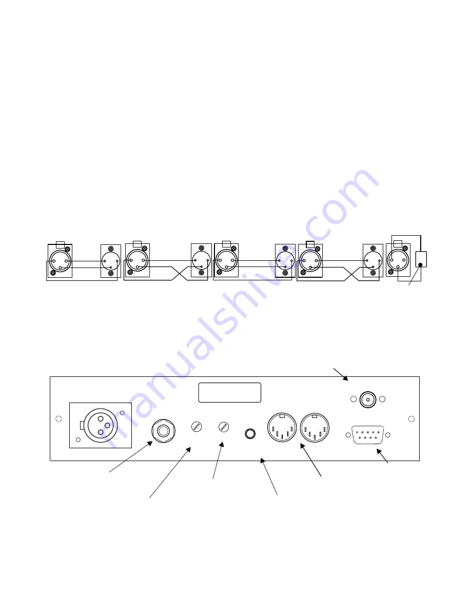
12. CONNECTING THE FIXTURES TO THE CONTROLLER
The controller transmits a standard DMX -512 signal. To assure proper functioning of the system , dip
switches on the fixtures must be set properly. Also appropriate cabling setup must be used. Here are some
practical suggestions.
1. A microphone type cable should be used , that is , two-conductor with a shield.
2 All XLR connections should be done in the following manner.
pin 1 = shield
pin 2 = DMX-
pin 3 = DMX+
3. The controller and the fixtures must be connected in series , that is, the output of the controller is
connected to the input of the first fixture , the output of the first fixture is connected to the input of the second
fixture , the output of the second fixture is connected to the input of the third fixture etc.
.
4. A 100 Ohm resistor MUST be installed at the output of the last fixture , between pins 2 and 3. This is
commonly called DMX TERMINATION.
5. Set dip switches on the fixtures according to the table on page 4.
NOTE !
Martin fixtures have pin 2 and pin 3 reversed. A “reversed” cable should be used so they may function
correctly.
22
RS 232
13. BACK PANEL VIEW
Power input.
The AC adapter is supplied with the unit.
RS-232 I/O
Computer Interface
MIDI Jacks
MARTIN
MARTIN
OTHER
FIXTURE
OTHER FIXTURE
CONTROLLER
1
1
1
2
2
2
3
3
3
DMX -
DMX +
1
2
3
1
2
3
SHIELD
SHIELD
SHIELD
SHIELD
DMX -
DMX -
DMX +
DMX +
1
2
3
1
2
3
1
2
3
1
2
3
DMX -
DMX +
TERMINATION
100 Ohm
CD Control Signal
MINI JACK
Audio Input
Stereo Jack
Audio sensitivity
adjustment.
LCD Contrast Adjustment
DMX OUT
MIDI
IN
OUT
AUDIO
775 mV
PWR
9V AC / 12 V DC
LCD
CONTRAST
CD
CONTROL SIGNAL
AUDIO
SENSITIVITY
Содержание Nadir PX102
Страница 1: ...OPERATION MANUAL PX102 Nadir R ...
Страница 26: ...FAQ 24 ...
Страница 27: ...NOTE 25 ...


