


AAM
−
136
Revised June 5, 2012
29
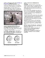
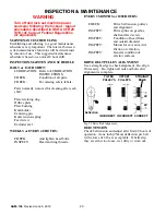
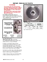
“NICKS” AT HOLE EDGES
RUSTY APPEARANCE OR
VISIBLE DISCOLORATION
Fig. 41 Orifice Plate Damage.
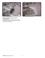
KNIFE INSERT REMOVAL (Fig. 42 )
Insert point of Insert Remover Tool into slot at
locating pin end of insert. Gently pry upward and
lift worn insert out of slot. Repeat for all inserts.
Discard worn inserts.
KNIFEHOLDER
INSERT REMOVER TOOL
INSERT
Fig. 42 Knife Insert Removal.
KNIFE INSERT INSTALLATION (Fig. 43 )
Line up the new insert over locating pin and push
gently down into insert slot. Tap new inserts in
place using a soft hammer. Replace inserts when
they have worn down
1/8”
(3mm) or more.
KNIFEHOLDER
INSERT
SOFT
HAMMER
Fig. 43 Knife Insert Installation.
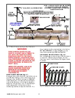
CENTERING PIN AND BUSHING (Fig. 44 )
Pins and bushings are not re
−
buildable and should
be replaced as often as is necessary. If total
clearance between pin and bushing bore is
1/32”
(.79mm) or more, replace both.
WEAR AREA
BUSHING
(BCA ONLY)
CENTERING PIN
WEAR AREA
Fig. 44 Centering Pin & Bushing.
KNIFE TENSION SPRING (Fig. 45 )
Knife tension springs may occasionally weaken,
break or get lost. Keep a good supply on hand.
1
−
3/8”
(35mm)
Fig. 45 Knife Tension Spring.