background image


86 

6.1.1  3D Intelligent Positioning Key 
In the middle of the eight direction arrows, there is a 3D intelligent positioning key. 
See Figure 6-4 . Click this button, system goes back to the single screen mode. 
Drag the mouse in the screen to adjust section size.  


Figure 6-4  

Here is a sheet for you reference. 

Name   Function 

key  

function 

Shortcut 
key  

Function 
 key 

function 

Shortcut 
 key 

Zoom 


Near  


Far  


Focus 


Near  


Far  


Iris 


close  


Open  


6.2

6.2

6.2

6.2


Preset  

Preset  

Preset  

Preset  ////PPPPatrol 

atrol 

atrol 

atrol ////    PPPPattern 

attern 

attern 

attern /Bo

/Bo

/Bo

/Border  

rder  

rder  

rder  FFFFunction 

unction 

unction 

unction     

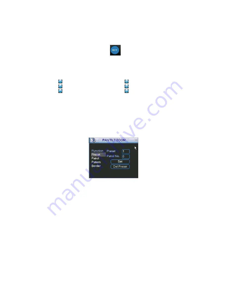
In Figure 6-2 click the set button. The interface is shown as below: 
Here you can set the following items: 

  Preset 

  Patrol 

  Pattern 

  Border 


Figure 6-5   

In Figure 6-2, click page switch button, you can see an interface as in Figure 6-6. 
Here you can activate the following functions: 

  Preset 

  Tour(Patrol) 

  Pattern 

  Auto scan 

  Auto pan 

  Flip 

  Page Switch 


Содержание PRX-MG04 Series

Страница 1: ...1 www protexitalia it Standalone DVR User s Manual PRX MG04x PRX MG08x PRX MG16x...

Страница 2: ...Remote Control Remote Control 17 2 4 2 4 2 4 2 4 Mouse Control Mouse Control Mouse Control Mouse Control 18 2 5 2 5 2 5 2 5 Virtual Keyboard Front Panel Virtual Keyboard Front Panel Virtual Keyboard F...

Страница 3: ...idirectional Audio Looping Video Matrix 24 3 7 1 Audio Input One Audio Output 25 3 7 2 Looping video 25 3 7 3 Matrix Video Output 26 3 7 4 Alarm Input and Relay Output 26 3 7 5 Alarm Input 26 3 7 6 Al...

Страница 4: ...nd Alarm Activation 45 4 6 1 Go to alarm setup interface 45 4 6 2 Alarm setup 45 4 7 4 7 4 7 4 7 Backup Backup Backup Backup 47 4 7 1 Detect Device 47 4 7 1 Backup 48 4 8 4 8 4 8 4 8 PTZ Control and C...

Страница 5: ...ule 60 5 3 4 RS232 60 5 3 5 Network 61 5 3 6 Alarm 68 5 3 7 Detect 68 5 3 8 Pan Tilt Zoom 68 5 3 9 Display 69 5 3 10 Default 71 5 4 5 4 5 4 5 4 Search Search Search Search 72 5 5 5 5 5 5 5 5 Advanced...

Страница 6: ...n Setup 88 6 2 6 Activate Pattern Function 88 6 2 7 Border Setup 88 6 2 8 Activate Border Function 88 6 2 9 Flip 88 7 7 7 7 WEB CLIENT OPERATION WEB CLIENT OPERATION WEB CLIENT OPERATION WEB CLIENT OP...

Страница 7: ...232 OPERATION 129 9 1 9 1 9 1 9 1 Network Connection Network Connection Network Connection Network Connection 129 9 2 9 2 9 2 9 2 Keyboard Keyboard Keyboard Keyboard 129 10 10 10 10 FAQ FAQ FAQ FAQ 13...

Страница 8: ...d to be a reference tool for the installation and operation of your system Here you can find information about this series DVR features and functions as well as a detailed menu tree Before installatio...

Страница 9: ...ineers We are not liable for any problems caused by unauthorized modifications or attempted repair 5 Environment The DVR should be installed in a cool dry place away from direct sunlight inflammable e...

Страница 10: ...otocols supported preset scan auto pan auto tour pattern auxiliary function supported And with our Speed Dome 3D intelligent positioning function supported Easy backup methods USB devices CD RW DVD RW...

Страница 11: ...Camera Adjustment Adjust color according to different time periods Video Information Camera title time video loss camera lock motion detection recording TV Output Adjustment Adjust TV output color di...

Страница 12: ...play next file previous file next camera previous camera full screen repeat shuffle backup selection Digital Zoom Selected zone can zoom into full screen during playback Backup Mode Flash stick USB HD...

Страница 13: ...oop Output Matrix Output Bidirectional Talk Input PRX MG04H 4 channel 4 channel 1 channel 1 channel PRX MG08H 4 channel 8 channel 1 channel 1 channel PRX MG16H 4 channel 16 channel 1 channel 1 channel...

Страница 14: ...standing by this lamp turns on Remote control signal receiver To receive signals from remote control 2 Function indication light In preview interface no other menu press this button for three seconds...

Страница 15: ...own Activate current control modify setup increase decrease numeral assistant function such as PTZ menu Left right shift current activated control When playback click these buttons to control playback...

Страница 16: ...WER Power button press this button for three seconds to shut down DVR 7 Power indication light Power indication light Note Turn shuttle outer ring clockwise stands for right counter clockwise stands f...

Страница 17: ...17 Figure 2 3 2 3 2 3 2 3 2 3 Remote Control Remote Control Remote Control Remote Control The remote control interface is shown as in Figure 2...

Страница 18: ...Fast play 16 Play Pause 2 4 2 4 2 4 2 4 Mouse Control Mouse Control Mouse Control Mouse Control System pops up password input dialogue box if you have not logged in In real time monitor mode you can g...

Страница 19: ...umeral in the on screen keyboard directly Implement special control operation such as double click one item in the file list to playback the video Double left click mouse In multiple window mode doubl...

Страница 20: ...rtual Keyboard Front Panel 2 5 1 Virtual Keyboard The system supports two input methods numeral input and English character small and capitalized input Move the cursor to the text column the text is s...

Страница 21: ...ecommend Seagate HDD of 7200rpm or higher 3 2 2 Calculate HDD Size This series have no limit to HDD capacity You can use 120G 750G HDD to guarantee higher stability The formula of total HDD size is To...

Страница 22: ...s 9 Place the upper cover back and screw firmly After HDD installation please check connection of data ribbon and power cord 3 3 3 3 3 3 3 3 CD CD CD CD DVD DVD DVD DVD Burner Burner Burner Burner Ins...

Страница 23: ...match or not We recommend you use UPS to guarantee steady operation DVR life span and other peripheral equipments operation such as cameras 3 6 3 6 3 6 3 6 C C C Connecting onnecting onnecting onnecti...

Страница 24: ...s case if your application requires a VGA monitor you have to press the button FN or Shift on the front panel NOTE Video output 1 and VGA can t display at the same time But Video output 2 can display...

Страница 25: ...eously which lets you control audio at the monitored location To set up audio 1 Make sure your audio input device matches the RCA input level If the device and RCA input levels do not match audio dist...

Страница 26: ...3 Verify the video from each source and troubleshoot as necessary Please refer to Figure 3 5 Figure 3 5 3 7 4 Alarm Input and Relay Output The DVR offers 16 alarm inputs for external signaling device...

Страница 27: ...r to Figure 3 7 for more information Figure 3 7 3 7 7 Alarm Input and Output Details You can refer to the following sheet and Figure 3 8 for alarm input and output information Parameter Grounding Alar...

Страница 28: ...t ALARM If you need to reset the touched off alarm remotely you can use DVR to supply controllable 12 V power to the alarm detector such as the smoke detector Use the same ground with that of DVR if y...

Страница 29: ...h different polarity 1000VAC 1minute 50 60Hz Insulation between touch and winding 1000VAC 1minute 50 60Hz Surge voltage between touches with same polarity 1500V 10 160us Length of open time 3ms max Le...

Страница 30: ...otocol the PTZ device can t return any data to the unit To enable the operation connect the PTZ device to the RS485 A B input on the DVR Since RS485 is disabled by default for each camera you must ena...

Страница 31: ...ssword 888888 administrator local only Username 666666 Passwords 666666 Lower authority user who can only monitor playback backup and etc Username default Password default hidden user For your system...

Страница 32: ...seconds system will stop all operations Then you can click the power button in the rear panel to turn off the DVR 4 1 4 Auto Resume after Power Failure The system can automatically backup video and r...

Страница 33: ...ual record menu Right click mouse or in the main menu Advanced Manual Record In live viewing mode click record button in the front panel or record button in the remote control Manual record menu is sh...

Страница 34: ...ication light in front panel will turn on Figure 4 7 All channel manual record Please highlight ALL after Manual See Figure 4 8 When system is in manual recording all scheduled set up you have set in...

Страница 35: ...n in the remote control Click search in the main menu Search interface is shown as below See Figure 4 10 Usually there are three file types R regular recording file A external alarm recording file M m...

Страница 36: ...erate accurate playback 4 3 2 3 Synchronized playback function when playback During playback process click numeral key system can switch to the corresponding channel video of the same time 4 3 2 4 Dig...

Страница 37: ...continue turning to get different speed In forward or backward mode double click Pause Play button to get normal playback Frame rate may vary due to different version Manual playback frame by frame I...

Страница 38: ...le list Figure 4 11 4 4 4 4 4 4 4 4 Record Setup Schedule Record Setup Schedule Record Setup Schedule Record Setup Schedule When the system boots up it is in default 24 hour regular mode You can set r...

Страница 39: ...click save button or you can finish all setup and then click save button to memorize all the settings 4 4 1 2 Redundancy Redundancy function allows you to memorize record file in several disks These f...

Страница 40: ...the channel you want to implement motion detection Event type from the dropdown list you can select motion detection type Channel select the channel to activate recording function once alarm occurred...

Страница 41: ...evel has the highest sensitivity Alarm output when alarm occurred system enables peripheral alarm devices Tour Here you can enable tour function when alarm occurs It is a one window tour Please go to...

Страница 42: ...42 Figure 4 15 Figure 4 16 Figure 4 17...

Страница 43: ...screen if you enabled this function Send email System can send out email to alert you when alarm occurs PTZ activation Here you can set PTZ movement when alarm occurs Such as go to preset tour patter...

Страница 44: ...alert you when alarm occurs PTZ activation Here you can set PTZ movement when alarm occurs Such as go to preset tour pattern when there is an alarm Click select button you can see an interface is show...

Страница 45: ...preset tour pattern when there is an alarm Click select button you can see an interface is shown as in Figure 4 25 Period Click set button you can see an interface is shown as in Figure 4 23 Here you...

Страница 46: ...r external alarm cancelled Tour Here you can enable tour function when alarm occurs It is a one window tour Please go to chapter 5 3 9 Display for tour interval setup Snapshot System can snapshoot whe...

Страница 47: ...RW DVD driver USB backup and network download Here we introduce USB backup first You can refer to Chapter 7 Web Client Operation for network download backup operation 4 7 1 Detect Device Click backup...

Страница 48: ...n backup selected files There is a process bar for you reference When the system completes backup you can see a dialogue box prompting successful backup Figure 4 26 Click backup button system begins b...

Страница 49: ...tion Please follow the procedures below to go on cable connection Connect the dome RS485 port to DVR 485 port Connect dome video output cable to DVR video input port Connect power adapter to the dome...

Страница 50: ...n Button in the front panel or click Fn key in the remote control The interface is shown as in Figure 4 29 Figure 4 29 Click Pan Tilt Zoom the interface is shown as below See Figure 4 30 Here you can...

Страница 51: ...n mode Drag the mouse in the screen to adjust section size It can realize PTZ automatically Figure 4 32 Here is a sheet for you reference Name Function key function Shortcut key Function key function...

Страница 52: ...o pan Flip Reset Page switch Figure 4 34 Note The following setups are usually operated in the Figure 4 30 Figure 4 33 and Figure 4 34 4 9 1Preset Setup In Figure 4 30 use eight direction arrows to ad...

Страница 53: ...trol tour For each patrol tour you can input max 80 presets Figure 4 36 4 9 4 Activate Patrol tour In Figure 4 33 input patrol tour number in the No blank and click patrol button 4 9 5 Pattern Setup I...

Страница 54: ...ft limit button Repeat the above procedures to set right limit Figure 4 38 4 9 8 Activate Auto Scan In Figure 4 34 click Auto Scan button the system begins auto scan Correspondingly the auto scan butt...

Страница 55: ...5 1 5 1 5 1 Menu Menu Menu Menu T T T Tree ree ree ree This series DVR menu tree is shown as below 5 2 5 2 5 2 5 2 Main Main Main Main M M M Menu enu enu enu After you logged in the system main menu...

Страница 56: ...there are three denotations to separate date dot beeline and solidus Snapshoot Here you can set image upload interval This function applies to some series only DST Here you can set DST time and date P...

Страница 57: ...y record duration Default value is 60 minutes DVR No when you are using one remote control to control several DVRs you can give a name to each DVR for your management Video standard There are two form...

Страница 58: ...ou can see an interface is shown in Figure 5 7 Cover area Privacy mask Here is for you to set window blanking section You can drag you mouse to set proper section size Preview monitor privacy mask has...

Страница 59: ...the corresponding function Figure 5 6 Figure 5 7 Figure 5 8 For RG S series it supports various settings for channel resolution and frame Resolution pixel PAL QCIF 176 144 CIF 352 288 HD1 352 576 2CIF...

Страница 60: ...ally whole resources are limited When you wan to enhance resource in one channel you need to reduce resource for other channel The system will pop up setup failure interface if the resource setup is b...

Страница 61: ...k Gateway display as o You need to disable DHCP function to view current IP information Besides when PPPoE is operating you can not modify IP Subnet mask Gateway TCP port Default value is 37777 System...

Страница 62: ...e click current item to go to setup interface Figure 5 11 5 3 5 2 IP Filter IP filter interface is shown as in Figure 5 12 You can add IP in the following list The list supports max 64 IP addresses Pl...

Страница 63: ...oup address 224 0 0 0 239 255 255 255 D address space The higher four bit of the first byte 1110 Reserved local multiple cast group address 224 0 0 0 224 0 0 255 TTL 1 When sending out telegraph For e...

Страница 64: ...in the PPPoE is the DVR dynamic value You can access this IP to visit the unit Figure 5 14 5 3 5 5 NTP Setup You need to install SNTP server Such as Absolute Time Server in your PC first In Windows X...

Страница 65: ...Figure 5 16 5 3 5 7 DDNS Setup DDNS setup interface is shown as in Figure 5 17 You need a PC of fixed IP in the internet and there is the DDNS software running in this PC In other words this PC is a...

Страница 66: ...gure 5 18 Figure 5 18 5 3 5 9 FTP You need to download or buy FTP service tool such as Ser U FTP SERVER to establish FTP service Please install Ser U FTP SERVER first From start program Serv U FTP Ser...

Страница 67: ...e folders under this FTP In Figure 5 10 select FTP and then double click mouse You can see the following interface See Figure 5 21 Figure 5 21 Please highlight the icon in front of Enable to activate...

Страница 68: ...ure 5 23 5 3 6 Alarm Please refer to chapter 4 6 Alarm Setup and Activation 5 3 7 Detect Please refer to chapter 4 5 Detect 5 3 8 Pan Tilt Zoom The pan tilt zoom setup includes the following items Ple...

Страница 69: ...tem is playback Overlay information System displays some information in the screen for your reference Display mode you can select from the dropdown list self adaptive VGA TV Enable tour activate tour...

Страница 70: ...nd only You need to refresh web or client end to get the latest channel name System max support 25 digital character Figure 5 26 In tour mode you can see the following interface On the right corner ri...

Страница 71: ...ncode Schedule RS232 Network Alarm Detect Pan tilt zoom Display Channel name Please highlight icon to select the corresponding function After all the setups please click save button system goes back t...

Страница 72: ...maintain and TV adjust Figure 5 29 5 5 1 HDD Management Here is for you to view and implement hard disk management See Figure 5 30 You can set proper mode for each hard disk from the dropdown list Whe...

Страница 73: ...m channel number ranges from 1 to 6 Delay value is from 0 to 240 seconds Please note when HDD capacity is not full system only alarms once After all the setups please click OK button system goes back...

Страница 74: ...d email System can send out email to alert you when alarm occurs Figure 5 32 5 5 3 Alarm Output Here is for you to set proper alarm output Please highlight icon to select the corresponding alarm outpu...

Страница 75: ...not be deleted When there is no login user hidden user default automatically login You can set some rights such as monitor for this user so that you can view some channel view without login One user...

Страница 76: ...ith other devices such as TV walls analog matrix and so on 5 5 8 2 Matrix outputs They are like the small scale matrix You can select any camera from our DVR to switch And the output can also tour bet...

Страница 77: ...o Video Matrix You can see an interface is shown as in Figure 5 39 Figure 5 39 5 5 8 5 2 Right Mouse Menu In one window display mode right click mouse to select Video Matrix See Figure 5 40 Figure 5 4...

Страница 78: ...5 42 You can follow the steps listed below Select local alarm The record channel function has been enabled and you have selected corresponding record channel The video matrix function has been enable...

Страница 79: ...tivate all the channels in the setup If system has toured some activation channels then corresponding alarm activation channels are null Figure 5 42 5 5 8 6 3 Motion Detection including video loss and...

Страница 80: ...activation channel after alarm completes Motion detection activation is almost the same as the alarm But it has different priority System will continue implementing scheduled tour in the following tw...

Страница 81: ...u add a new one Once there is a hard disk confliction please check hard disk time and system time is the same or not Please go to setting then general to modify system time At last reboot the system t...

Страница 82: ...ration data management alarm event record operation log clear and etc Pleased select start time and end time then click search button You can view the log files Please page up down button to view if t...

Страница 83: ...5 7 5 7 5 7 5 7 Exit Exit Exit Exit Double click exit button system pop up a dialogue box for you to select See Figure 5 50 Logout menu user log out menu You need to input password when you login the...

Страница 84: ...84 Figure 5 50...

Страница 85: ...in the front panel or click AUX key in the remote control The interface is shown as below See Figure 6 1 Figure 6 1 Click Pan Tilt Zoom the interface is shown as in Figure 6 2 Here you can set the fol...

Страница 86: ...cut key Zoom Near Far Focus Near Far Iris close Open 6 2 6 2 6 2 6 2 Preset Preset Preset Preset P P P Patrol atrol atrol atrol P P P Pattern attern attern attern Bo Bo Bo Border rder rder rder F F F...

Страница 87: ...Figure 6 5 click preset button and input preset number The interface is shown as in Figure 6 7 Add this preset to one patrol number Figure 6 7 6 2 2 Activate Preset In Figure 6 6 please input preset n...

Страница 88: ...er Setup In Figure 6 5 click border button The interface is shown as in Figure 6 10 Please go to Figure 6 2 use direction arrows to select camera left limit and then please go to Figure 6 10 and click...

Страница 89: ...89 Figure 6 11...

Страница 90: ...atible with WIN VISTA web control right now But you need to disable user account control function Double click user account and then disable user account control After completing setup please reboot t...

Страница 91: ...lows See Figure 7 2 Figure 7 2 After installation the interface is shown as below See Figure 7 3 Please input your user name and password Default factory name is admin and password is admin Note For s...

Страница 92: ...Section 4 real time monitor window Please note current preview window is circled by a green rectangle zone Section 5 Here you can view window switch button You can also select video priority between...

Страница 93: ...de 3 Local record When you click local record button the system begins recording and this button becomes highlighted You can go to system local record to set video file path 4 Capture picture You can...

Страница 94: ...Figure 7 10 7 2 2 1 Direction key and 3D positioning key In Figure 7 10 there are eight direction keys In the middle of the eight direction keys there is a 3D intelligent positioning key Click SIT bu...

Страница 95: ...key Function Function key Function Zoom Near Far Focus Near Far Iris close Open Then click triangle icon in Figure 7 10 you can see the following interface See Figure 7 11 Figure 7 11 In Figure 7 11...

Страница 96: ...to Figure 7 11 to implement camera operation Then you can click stop record button Now you have set one pattern 7 2 2 6 Preset In Figure 7 12 move the camera to your desired location and then input pr...

Страница 97: ...htness contrast hue and saturation Current channel border becomes green Or you can click default button to use system default setup Figure 7 14 7 2 4 Picture Path and Record Path Click more button in...

Страница 98: ...nterface Switch Put your mouse on the PTZ control bar until you see the following icon See Figure 7 18 Figure 7 18 Left click your mouse and then drag it to the channel control status bar You can see...

Страница 99: ...re Configure Configure In the main window click config button you can see an interface is shown as in Figure 7 20 Figure 7 20 7 3 1 System Information Click device configuration button you can see the...

Страница 100: ...100 Figure 7 21 Version Click version button you can see corresponding HDD information for your reference See Figure 7 22 Figure 7 22...

Страница 101: ...you can view HDD amount HDD status total volume and free space See Figure 7 23 Figure 7 23 Log Click log button you can see an interface is shown as in Figure 7 24 Here you can view current device log...

Страница 102: ...mat Here you can select data format from the dropdown list Data separator Please select separator such as or Time format there are two options 24 H and 12 H HDD full there are two options stop recordi...

Страница 103: ...m AV enable Video Audio System only displays video by default You need to manually enable audio function Bit rate There are two options CBR and VBR You can only set video quality in VBR mode Frame rat...

Страница 104: ...alarm record A Channel select the channel number you desire Week you can select from the dropdown list Or you can select at the bottom of the interface Prerecord system can record the three to five s...

Страница 105: ...igure 7 27 Figure 7 28 Tip After you finished setup for one channel you can click save as button system pops up the following interface See Figure 7 29 Now you can copy one channel setup to other chan...

Страница 106: ...TTP port default setup is 80 Transfer here you can select the priority between fluency video quality Enable PPPoE In remote item enable PPPoE function and then input PPPoE name and PPPoE password you...

Страница 107: ...er IP DDNServer default htm for example input http 10 5 2 149 DDNServer default htm you open a DDNS server web page Figure 7 31 RS232 RS232 includes the following items See Figure 7 32 Function There...

Страница 108: ...108 Figure 7 32 Mul DDNS Here you can select DDNS type This operation needs DVR device supported See Figure 7 33 Figure 7 33 FTP...

Страница 109: ...le If the file is larger than the setup value system only uploads the setup value data and ignores the rest data Interval for one channel of the same record type if there is more than one alarm system...

Страница 110: ...o select alarm record in DVR schedule interface and enable schedule function in manual record interface Alarm output select alarm activation channel when alarm occurs Please note channel 3 is to contr...

Страница 111: ...ame from the dropdown list Type There are three types motion detection Video loss Camera mask detection Record channel Here you can select record channel Multiple choices Please make sure you have set...

Страница 112: ...se you can go to full screen display mode Do remember clicking OK button in Figure 7 41 to save your motion detection zone setup Alarm output Here you can select activated external peripheral device w...

Страница 113: ...113 Figure 7 39 Figure 7 40 Figure 7 41...

Страница 114: ...ing dome protocol such as Pelco Address Set corresponding dome address Default value is 1 Please note your setup here shall comply with your dome address otherwise you can not control the speed dome B...

Страница 115: ...nfig button you can load a setup file Figure 7 44 Figure 7 45 7 3 2 1 Advanced Advanced includes the following items See Figure 7 46 Account HDD management Alarm input Alarm output Auto maintain Video...

Страница 116: ...116 Figure 7 46 Click add group button you can see the following interface See Figure 7 47 Here you can add one new group and then select corresponding rights for the whole group accounts...

Страница 117: ...ser button you can see the following interface See Figure 7 48 Here you can input a new user and then select corresponding rights Please note one user must belong to one group and user right shall not...

Страница 118: ...n not support large overload It shall be less than 1A Too heavy current may result in relay damage Please use contactor if necessary Figure 7 49 HDD management This function needs DVR device supported...

Страница 119: ...119 Figure 7 50 Auto maintenance Auto maintenance interface is shown as in Figure 7 51 Here you can enable auto reboot or auto delete old files function Need DVR supported Figure 7 51...

Страница 120: ...o matrix interface is shown as in Figure 7 52 Please note this function needs DVR supported Figure 7 52 Snap Picture Snapshoot interface is shown as in Figure 7 53 Please note this function needs DVR...

Страница 121: ...gure 7 54 Please use page up down key to view the search results Double click file name you can view the file and system will automatically backup the image in you installation directory Figure 7 54 I...

Страница 122: ...d button System pops up a dialogue box asking you specify directory See Figure 7 56 Figure 7 56 Then you can input file name and click save to backup file in your local pc During the download process...

Страница 123: ...123 Figure 7 57 7 5 7 5 7 5 7 5 Alarm Alarm Alarm Alarm Here you can set alarm type and alarm prompt audio file See Figure 7 58 Figure 7 58...

Страница 124: ...log out button system goes back to log in interface See Figure 7 60 Figure 7 60 7 8 7 8 7 8 7 8 Un Un Un Un install install install install W W W Web eb eb eb C C C Control ontrol ontrol ontrol You c...

Страница 125: ...g in Double click enterprise profession surveillance platform icon If it is your first time to use the system you can see the following interface See Figure 8 1 Figure 8 1 After selecting a language y...

Страница 126: ...M M Monitor onitor onitor onitor After successfully logged in please select the device and then click connect disconnect button Select the channel you wan to view click connect disconnect button again...

Страница 127: ...one window in full screen Here we recommend resolution 1024 768 Select a device name and then click connect disconnect button you can connect current device to network You can see a little red cross b...

Страница 128: ...128 Figure 8 5 Add device Add organization structure...

Страница 129: ...the DVR supports matrix protocol or not 9 2 9 2 9 2 9 2 Keyboard Keyboard Keyboard Keyboard Control keyboard is very convenient for multi DVR control menu options and PTZ control Select keyboard cont...

Страница 130: ...ng environment is too harsh too much dust Hardware malfunction 3 System can not detect hard disk There are following possibilities HDD is broken HDD ribbon is damaged HDD cable connection is loose 4 T...

Страница 131: ...power picker It is not a power acoustics Audio cable is damaged DVR hardware malfunctions 9 There is audio when monitor but there is no audio when system playback There are following possibilities Set...

Страница 132: ...ht now our DVR is not compatible with Windows VISTA control ActiveX control has been disabled No dx8 1 or higher Please upgrade display card driver Network connection error Network setup error Passwor...

Страница 133: ...Alarm output has been open manually Input device error or connection is not correct Some program versions may have this problem Please upgrade your system 19 Alarm function is null There are followin...

Страница 134: ...via media player No DivX503Bundle exe or ffdshow 2004 1012 exe in Windows XP OS 23 Forget local menu operation password or network password Please contact your local service engineer or our sales per...

Страница 135: ...firmed according to Formula 2 to calculate the storage capacity i m which is storage of each channel needed unit Mbyte i m i q i h i D 2 In the formula i h means the recording time for each day hour i...

Страница 136: ...zer Freedom 256M Sandisk Cruzer Freedom 512M Sandisk Cruzer Freedom 1G Sandisk Cruzer Freedom 2G Kingston DataTraveler 1G Kingston DataTraveler 2G Kingston DataTraveler 1G Kingston DataTraveler 2G Max...

Страница 137: ...th the model recommended to set USB burner Manufacturer Model Interface Type Sony DRU 835A IDE DVD RW Sony DW Q120A IDE DVD RW Sony DW G120A IDE DVD RW Sony CRX 230AE IDE CD RW Sony CRX 320A IDE CD RW...

Страница 138: ...330AS 750G SATA Seagate Barracuda 11 ST3500320AS 500G SATA Maxtor DiamondMax 20 STM3320820AS 320G SATA Maxtor DiamondMax 20 STM3250820AS 250G SATA Maxtor DiamondMax 21 STM3160211AS 160G SATA Maxtor Di...

Отзывы: