background image

18


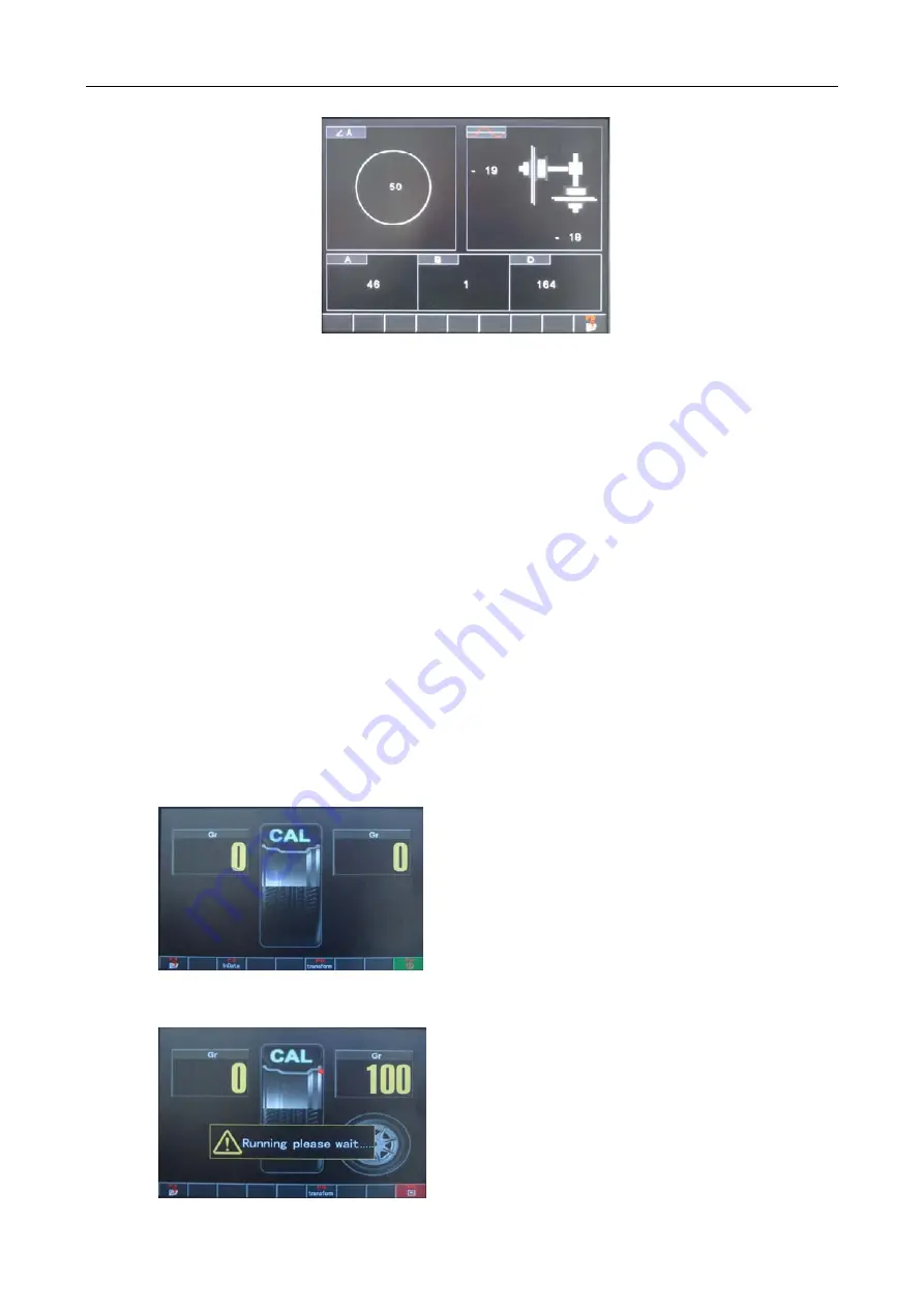
Phrase angle: The Left top corner in the interface of figure 43 is phrase angle test. 
Rotate the wheel and check if the phrase angle sensor reacts or if there is value 
displayed.. 
Piezoelectric sensor: The right top corner in the interface of figure 43 is piezoelectric 
test. Press the wheel to check if the piezoelectric sensor reacts and if there is value 
or position change displayed. 
Automatic gauge: Pull the gauge to see if A and D measuring signals react and the 
values change; Turn on Gauge B (if it is available) and check if B signal reacts and 
value changes. 

7.11.3 Unbalance Calibration 

The third section of program settings is unbalance calibration. It is used to initialize 
the new machine and remove the old equipments’ measurement errors caused by 
total loss from use , parts ageing and replacing, or strong impact. 
Choose a wheel with small unbalanced value and install it on the balancer. Input the 
wheel parameters then calibrate it as shown in figure 46. 


Rotate the wheel to calibrate for the first time 
without placing standard counterweight. 


Rotate the wheel to calibrate for the second 
time by placing a counterweight of 100g on the 
outside of rim. 
 

Figure 43 

Figure 44 

Figure 45 

                                                          WB-514 Wheel Balancer user’s manual 

Содержание WB-514

Страница 1: ...V1 00 000 2012 08 20...

Страница 2: ...on may be reproduced stored in a retrieval system or transmitted in any form or by any means electronic mechanical photocopying recording or otherwise without the prior written permission of PROTEC Th...

Страница 3: ...wheel balancer WB 511 This unit is made for the purpose of persons who have special techniques and certifications Safety Instructions z Make sure all operators are properly trained Improper operation...

Страница 4: ...ATING INSTRUCTIONS 7 1 SELF CHECK 7 2 INSTALLING WHEEL 7 3 WHEEL PARAMETERS INPUT 7 3 1 Input Wheel Parameters with Automatic Gauge 7 4 STANDARD DYNAMIC MODE 7 5 STATIC MODE 7 6 ALU1 ALU5 MODES 7 7 AL...

Страница 5: ...7 11 3 Unbalance Calibration 7 11 4 Automatic Gauge Calibration 8 PROMPT INFORMATION APPENDIX I APPENDIX II APPENDIX WB 514 Wheel Balancer user s manual...

Страница 6: ...se the manufacturer will not be responsible for the damage caused by improper transportation or operation z To use the equipment beyond its measurement range may cause damage to it and can not ensure...

Страница 7: ...calibration z Guard Protection z Self check Error and Diagnostics z Multi language Chart Article Interface the User Friendly Design Built in Operating Guide 2 3 Specifications z Power Supply 110V 220V...

Страница 8: ...packing list Check whether the machine surface is in good condition and whether there is loss or damage to the parts z Dismount the bolts on the base and make the balancer steadily rest Please do not...

Страница 9: ...e balancer 6 Control Unit F1 F9 are classic function keys whose functions are given by the prompt article appearing on the bottom of LCD screen Keypad tone can be on or off by the built in system opti...

Страница 10: ...8 is preferable because it approximates to installing wheel on a real car 7 3 Wheel Parameters Input Unlike ALU1S and ALU2S which need 4 parameters other modes need 3 parameters Parameter values are...

Страница 11: ...value interface indicates that Gauge A is selected Press to modify the current value The increasing or decreasing range equals the step set by the setting state eg If the step is 0 5 inch To press on...

Страница 12: ...he rule Place a counterweight of 34g on the 12 O clock position outside the wheel Keep rotating the wheel and stop rotating when the red triangle cursor on the left moves to the middle of the rule Pla...

Страница 13: ...side of the screen displays the unbalance value Rotate the wheel with hands and stop rotating when the red triangle cursor moves to the middle of the rule figure 20 Place a counterweight of 20g on th...

Страница 14: ...to assist in sticking counterweights 7 7 ALU1S ALU2S Modes ALU1S and ALU2S use automatic gauge to input the accurate size of the correction plane refer to figure 21 The differences between them are AL...

Страница 15: ...cting ALU1S has to choose two proper correction planes on both sides of rim ALU2S only choose one proper correction plane on the outside of rim Clean the position to be used to get ready for being stu...

Страница 16: ...step is 0 5 inch To press once will increase by 0 5 inch While inputting parameters press to convert the unit of parameters like mm or inch Input finished Press to save and return 7 7 2 ALU1S ALU2S Mo...

Страница 17: ...e if at any other position So it is better to use the brake pedal to locate it at 12 o clock and do the following operation Pull the gauge at the correction plane position pick up a counterweight of 5...

Страница 18: ...ress to return to the previous interface Take 8 spokes as an example In the interface of figure 29 Press F6 to choose an 8 spoke wheel according to the prompt at the bottom of the screen A red line su...

Страница 19: ...to determine the best mating of tire and rim When doing dynamic and static modes if the static mode value is greater than OPT value default 30g the key will appear on the screen figure 34 and the sys...

Страница 20: ...n press START key to do OPT measurement as shown in figures 36 37 After measurement rotate the wheel as shown in figure 38 Mark again on the outside tire of the marked point with the chalk Assemble th...

Страница 21: ...cycle fixtures and extending arms see 7 4 7 11 Setting Programs It includes system setting system testing unbalance calibration automatic gauge calibration and system information refer to figure 41 Ac...

Страница 22: ...s direction key to choose the item to be modified The red horizontal line under the corresponding item means that this item is in the state of editing Press key to modify the current value Confirm it...

Страница 23: ...ble and check if B signal reacts and value changes 7 11 3 Unbalance Calibration The third section of program settings is unbalance calibration It is used to initialize the new machine and remove the o...

Страница 24: ...ent errors caused by total loss from use parts ageing and replacing or strong impact The procedure is shown in the following figure The fourth section of program setting is automatic gauge calibration...

Страница 25: ...edge of the rim with the gauge tip to measure the rim diameter If it doesn t accord with the actual value modify it by pressing Confirm it and press to save and return Gauge D calibration finished Opt...

Страница 26: ...artificially during rotation measurement the balancer stops suddenly and prompt is given Prompt is given and measurement is stopped when rotating speed is too low to meet the basic measurement needs...

Страница 27: ...Appendix I WB 514 Wheel Balancer user s manual...

Страница 28: ...Appendix II WB 514 Wheel Balancer user s manual...

Страница 29: ...Appendix WB 514 Wheel Balancer user s manual...

Страница 30: ...25 WB 514 Wheel Balancer user s manual...

Страница 31: ...firmation representation or warranty concerning PROTEC automotive meters except as stated herein Disclaimer THE ABOVE WARRANTY IS IN LIEU OF ANY OTHER WARRANTY EXPRESSED OR IMPLIED INCLUDING ANY WARRA...

Отзывы: