


3
Factory Setting
Switch
Default Options Comments
NOTES - Heat Pump Systems
[1]
If batteries are installed the 24 Volt AC common connection is optional.
[2]
Select
O
for cool active or
B
for heat active.
[3]
Install a field supplied jumper between the
W2
and
E
terminals if
there is no separate emergency heat relay installed.
Provide disconnect and overload protection as required.
CONV / HP CONV
F / C
F
HE / HG
HG
Set Installer Switches
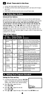
4
CONV Select for conventional systems
HP
Select for heat pump systems
F
Select for fahrenheit temperature scale
C
Select for celsius temperature scale
HG
Select for gas heat
HE
Select for electric heat
Typical Wiring Configurations
NOTE:
The “Installer Switch” option will be configured in the next step.
Heat Pump Systems
1 HEAT / 1 COOL - No Auxiliary Heat
Set Installer Switch to
HP
Rh
24 Volt AC Power
Rc
Connected to Rh with supplied Jumper Wire
O or B
Changeover Valve
[note 2]
Y1
Compressor Relay
G
Fan Relay
C
24 Volt AC Transformer Common
[note 1]
2 HEAT / 1 COOL - Including Auxiliary Heat (PRS4210 only)
Set Installer Switch to
HP
Rh
24 Volt AC Power
Rc
Connected to Rh with supplied Jumper Wire
O or B
Changeover Valve
[note 2]
Y1
Compressor Relay (1st stage heating/cooling)
W2
Auxiliary Heat Relay (2nd stage heating)
[note 3]
E
Emergency Heat Relay
[note 3]
G
Fan Relay
C
24 Volt AC Transformer Common
[note 1]
The Installer switches are located on the back of the thermostat and must
be properly set for this thermostat to operate properly.
The reset button
must be pressed after making any changes to these switches.


