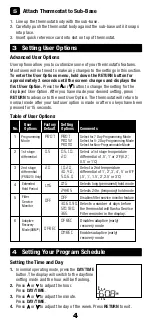
background image

2


1 HEAT / 1 COOL Single or Dual Transformer 


Set Installer Switch to 

CONV

 Rh

  24 Volt AC Power (heating transformer) 

[note 2]

 Rc

  24 Volt AC Power (cooling transformer) 

[note 2]

 W1

  Heat Relay (appears as 

W1/E

 on PRS4210)

 Y1

  Compressor Relay

 G


Fan Relay

 C


24 Volt AC Transformer Common 

[note 1, 3]

Typical Wiring Configurations

NOTE:


The “Installer Switch” option will be configured in the next step.

Conventional Systems


Connect Your Wires

3   

NOTES - Conventional Systems

[1]

 If batteries are installed the 24 Volt AC common connection is optional

[2]

 Remove factory installed jumper for dual transformer systems

[3]

 In dual transformer systems, transformer common must come from  


cooling transformer

[4]

 If needed for system

Provide disconnect and overload protection as required.


2 HEAT / 1 COOL Single or Dual Transformer (PRS4210 Only)


Set System Type to 

CONV

 Rh


24 Volt AC Power (heating transformer) 

[note 2]


Rc


24 Volt AC Power (cooling transformer) 

[note 2]

 W1


Heat Relay Stage 1

 Y1


Compressor Relay Stage 1

 Y2


Compressor Relay Stage 2

 [note 4]

 G


Fan Relay

 C


24 Volt AC Transformer Common 

[note 1, 3]


Heat Only or Millivolt 


Set Installer Switch to 

CONV


Rh

  Power Connection


 W

  Heat Relay (appears as 

W1/E

 on PRS4210)


 G

  Fan Relay 

[note 4]


 C

  24 Volt AC Transformer Common 

[note 1]

Содержание PRS4110

Страница 1: ...d service technicians only Read all instructions before proceeding This thermostat is compatible with Single stage heat cool conventional and heat pump systems Conventional systems up to 2 heat 2 cool...

Страница 2: ...rovide Power 3 Connect Your Wires 4 Set Installer Switches 5 Attach Thermostat to Sub Base Install the Sub Base Remove the sub base from the body of the thermostat Mount the sub base as shown below 1...

Страница 3: ...optional 2 Remove factory installed jumper for dual transformer systems 3 In dual transformer systems transformer common must come from cooling transformer 4 If needed for system Provide disconnect an...

Страница 4: ...e Installer Switch option will be configured in the next step Heat Pump Systems 1 HEAT 1 COOL No Auxiliary Heat Set Installer Switch to HP Rh 24 Volt AC Power Rc Connected to Rh with supplied Jumper W...

Страница 5: ...RO 7 Select for 7 Day Programming Mode Mode PRO 52 Select for 5 2 Day Programming Mode PRO NO Select for Non Programmable Mode 2 1st stage 0 5 0 5 1 0 Select a 1st stage temperature differential 2 0 d...

Страница 6: ...ling in each of your 4 daily events If you wish to use these settings then no further programming is necessary MORN DAY EVE NIGHT Time 6 00 pm Heat 70 F 21 C Cool 78 F 26 C Time 8 00 am Heat 62 F 17 C...

Страница 7: ...o adjust the temperature for the MORN event Press PROG 6 Repeat steps 3 6 for the DAY EVE and NIGHT events 7 If needed repeat steps 2 6 to program the opposite mode HEAT or COOL 8 Press RETURN to exit...

Страница 8: ...ram the opposite mode HEAT or COOL 9 Press RETURN to exit 5 Operating Your Thermostat Setting the System Control Mode The System Control has several modes of operation that can be selected by moving t...

Страница 9: ...Event Indicators Program Event Indicators appear in the display to let you know what part of your current program is active The 4 different program event indicators are MORN DAY EVE and NIGHT When th...

Страница 10: ...ARTS warrants each new PROSTAT thermostat against any defects that are due to faulty material or workmanship This warranty and our liability does not apply to batteries nor does it include damage to m...

Страница 11: ...das Rango de control 7 32 C 45 90 F Precisi n de la temperatura 5 C 1 F Terminaciones PRS4110 Rc Rh O B Y1 W1 G C PRS4210 Rc Rh O B Y1 Y2 E W1 G W2 C 1 Especificaciones PRS4110 100 02 Manual de Usuari...

Страница 12: ...2 Suministre energ a 3 Conecte los cables 4 Configure los interruptores de instalaci n 5 Fije el termostato a la sub base Instale la sub base Retire la sub base del cuerpo del termostato Monte la sub...

Страница 13: ...or de calefacci n nota 2 Rc Energ a a 24 voltios de CA transformador de aire acondicionado nota 2 W1 Rel de calefacci n etapa 1 W2 Rel de calefacci n etapa 2 Y1 Rel del compresor etapa 1 Y2 Rel del co...

Страница 14: ...del transformador a 24 voltios de CA nota1 NOTAS Sistemas de bomba de calor 1 Si las bater as est n instaladas la conexi n com n a 24 voltios de CA es opcional 2 Seleccione O para aire acondicionado...

Страница 15: ...durante 15 segundos 1 PRO 7 PRO 7 PRO 52 PRO NO Tabla de las opciones del usuario Valor pre Opciones determinado Opciones de No del usuario de f brica configuraci n Comentarios 2 Diferencial de 0 5 0...

Страница 16: ...ato ha sido configurado con una de las siguientes opciones de programaci n Modo de programaci n de 7 d as con 4 eventos por d a valor original Modo de programaci n de 5 2 d as con 4 eventos por d a Mo...

Страница 17: ...y programar toda la semana los 7 d as con un horario de programa de 4 eventos Configuraci n de los 7 d as al mismo tiempo SpeedSet NOTA La configuraci n de los 7 d as a la vez reemplazar cualquier d...

Страница 18: ...ramar 6 Presione o para ajustar la temperatura para el evento MORN Ma ana Presione PROG Programar 7 Repita los pasos 4 a 6 para sus eventos de DAY D a EVE Tarde y NIGHT Noche 8 Si es necesario repita...

Страница 19: ...interruptor de FAN ventilador a la posici n adecuada AUTO Autom tico El ventilador del sistema funcionar s lo cuando su sistema de calefacci n o aire acondicionado est funcionando ON Encendido El vent...

Страница 20: ...puje suavemente el cuerpo del termostato de nuevo en su base NOTA Recomendamos el remplazo anual de las bater as o si el termostato estar desatendido por un periodo largo Limpieza del termostato No ro...

Отзывы: