background image


P-6 

Installation Guide 

How does a relay work? 
The basic relay consists of a coil and a set of contacts. The most common relay mechanism is the 

electromagnetic mechanism. When voltage is applied to the coil, current passes through the wire and creates a 

magnetic field. This magnetic field pulls the contacts together and holds them until the current flow in the coil 

has stopped. 

Relays come in all varieties and types, but for the applications that concern us, we will concentrate on the 

single pole double throw (SPDT) 12 volts relay. 
Naming Convention 
Usually the relay’s manufacturer will include an electrical diagram on the relay displaying the role of each 

terminal and how they interact with each other. 

These terminal numbers are standard, and can be used with any SPDT relay. 

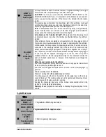
85 & 86: The coil. These inputs energize the coil when one is +12 volts, and the other is negative. They are 

usually non-polarized, so it does not matter which one is positive (+) or negative (-). 

87: Normally Open (N/O). When the coil is energized, 87 is connected to 30. 

87A: Normally Closed (N/C). When the coil is at rest, 87A is connected to 30.  

30: Common. When the relay is at rest, 30 is connected to 87A, when the coil is energized, it is then moved 

and makes contact with 87. (Note: in a SPDT relay, 30 can never be connected to 87 and 87A at the same 

time, 30 is connected to either 87 or 87A) 
What happens 
When there is no voltage across the coil (terminals 85 and 86), the relay's movable contact arm (connected to 

terminal 30) is held, by spring tension, against terminal 87A (normally closed circuit). 

When 12 volts is applied to the coil (terminals 85 and 86), the arm (connected to terminal 30) is pulled by the 

electromagnet (coil) so that it physically connects to terminal 87 (normally open circuit). 

When 12 volts is applied to the coil (terminals 85 and 86), the arm (connected to terminal 30) is pulled by the 

electromagnet (coil) so that it physically connects to terminal 87 (normally open circuit). 

Remember, there is no polarity on a relay’s coil. This means that you may apply positive from the battery to 

either terminal 85 or 86, and then ground the other terminal to activate the relay. In other words, you may use 

either a positive or negative trigger to energize the relay. 

Keep in mind, when the relay is energized, if the positive or the ground connection on the coil is broken, the 

arm switches the connection between 30 back from 87 to 87a. 
Quenching Diodes 
It was said earlier that a relay energizes itself by applying positive from the battery to either 85 or 86 and 

grounding the other terminal. This is not absolutely true, some relays are “polarized” if they have a quenching/ 

suppression diode (A diode installed between the coil terminals 85 and 86, could be internal or external). 

To activate the coil on this type of relay, make sure that the +12 volts trigger is on the same terminal of the 

relay as the anode (+ or non striped side) side of the quenching/suppression diode, and that the negative 

trigger is on the same terminal of the relay as the cathode (- or striped side) of the quenching/ suppression 

diode. 

When a relay’s coil is energized, a magnetic field is created and energy is stored in the coil. When power is 

removed from the coil, the magnetic field collapses. This causes a reverse voltage to be generated and can 

sometimes reach 200 volts. A quenching diode absorbs this reverse voltage spike. 
A closer look at a relay 
Now that you know what the main inscriptions are on the relay, take a look on the side, and you will see another 

inscription: 12 VDC, 40/ 30 A. 

12 VDC: This indicates the coil voltage rating. For an automotive relay, it's usually 12 volts DC. 

40/ 30 A: This indicates the current carrying capability of the contacts 30, 87, & 87A. 

40: Indicates that the normally closed circuit (30 and 87a) can safely handle a maximum of 40 amps of current. 

30: Indicates that the normally open circuit (30 and 87) can safely handle a maximum of 30 amps of current. 

Examples: 
The following examples demonstrate some of the most common uses for relays: isolation, inversion, 

interruption, strengthening current, and for powering multiple wires from one source safely.


Содержание CT-4211TW

Страница 1: ... guide carefully before beginning any work Warning Before installing the unit if installing on a vehicle with a manual transmission test that the OEM Door Switch contacts of the vehicle work well and that the Parking Brake system operates properly If installing on a vehicle with an automatic transmission test that the vehicle does not start when the gearshift lever is in the Drive position If it s...

Страница 2: ... 20 Tach Learning 21 Tach Jumper Settings 21 Multi Speed Tach Programming Procedure 21 Auto Tach Programming Procedure 21 Hybrid Option 21 Setting the Unit into Ready Mode 22 Horn Timing Adjustment 23 Arming and Disarming the Starter Kill 23 Installation Programmable Features 24 Ignition Controlled Door Locks 24 Secure Lock 24 LED Flashing 24 Safe Start 25 Engine Run Time 25 Idle Mode 25 Turbo Mod...

Страница 3: ... 1 Antenna 1 remote 1 Parts bag 1 Antenna interconnect cable 1 Quick guide 1 Harness kit 1 User guide Installation Tools Here is a list of basic tools and supplies you will need to test and install safely Digital Multi Meter DMM Computer safe logic probe Fused jumper wire Neon trouble light that is carpet safe Fender protector Carpet protector Soldering Iron solder electrical tape wire tie straps ...

Страница 4: ... off Note The Parking Light output relay in the module gives two clicks per flash 1 click for ON and 1 click for OFF Parking Light flashes referred to in this manual refer to the Parking Light output of the module INDUSTRY CANADA USER NOTICE Operation is subject to the following two conditions 1 this device may not cause interference and 2 this device must accept any interference including interfe...

Страница 5: ...uld be removed during the pre wire stage The fuses will not be put back in until the powering stage of the installation Connect all the necessary accessories to the module before mounting it in the vehicle Use tie straps to secure it to the vehicle Make sure the module and harnessing do not interfere with any moving parts and do not obstruct access to diagnostic ports or fuse boxes It should be up...

Страница 6: ...ber there is no polarity on a relay s coil This means that you may apply positive from the battery to either terminal 85 or 86 and then ground the other terminal to activate the relay In other words you may use either a positive or negative trigger to energize the relay Keep in mind when the relay is energized if the positive or the ground connection on the coil is broken the arm switches the conn...

Страница 7: ... the windshield wipers during remote starts Solution When power is applied to the OEM park light wire it back feeds through the park light switch and activates the wipers Where the connection was made from the start module s park light output and the vehicle s park light circuit the OEM park light wire is cut to isolate the park light switch and the actual parking lights A relay is added to the pa...

Страница 8: ...Connects to the key side of the cut OEM starter wire 30 Connects to the starter side of the cut OEM start wire Comments At rest the relay is not active and 12 volts on the starter wire passes through the relay through 87A 30 normally The starter disable output wire on the remote start module is activated when the LOCK button is pressed on the remote control When a theft attempt happens and the thi...

Страница 9: ...n the crank position the other wire will also read 12 volts this is the solenoid side wire To confirm you have a direct feed clutch switch hot wire the solenoid side wire with a fused 12 volts and the starter motor will crank Connect the starter output from the remote starter to solenoid side wire Note In the next two systems a Relay in the vehicle interrupts the start wire between the Ignition sw...

Страница 10: ...e circuit The Polarity of the Trigger wire does not matter in this system since all you need to do in order to bypass it is to use a relay to interrupt it during remote starts Harness Description When connecting the Module it is important to make sure the connector with the Ground wire is connected first before making the 12 volt connections Should the unit be powered before being grounded there c...

Страница 11: ...1 5 Hz or faster at idle Common Tach references are the negative side of an injector the negative side of an Ignition Coil Camshaft sensor Crankshaft sensor or the Engine Control Module ECM NOTE A Tach signal that is too low will cause the Module to over crank and a Tach signal that is too high will cause the Module to under crank 3 GRAY Hood Switch input Connect this wire to the Hood Pin switch s...

Страница 12: ...cted to a Single Pole Double Throw Relay This wire will connect to Pin 85 on the Relay and Pin 86 will be connected to the Ignition wire A second benefit of the Starter Kill is the Anti Grind feature When the vehicle has been remote started the Anti Grind prevents the starter motor from re engaging when the ignition key is inserted in the Ignition switch and accidentally turned to the CRANK positi...

Страница 13: ...e module must be connected to the Glow plug indicator light of the vehicle The module will only accept positive Glow plug input signals if the signal is negative use a relay to invert its polarity A diode must be added between the negative Glow plug trigger on the relay and the negative Glow plug wire of the car This is to prevent feedback effects on the Glow plug indicator light on the instrument...

Страница 14: ...o activate one of the three possible functions you must place the jumper supplied on one of the three sets of pins and connect the 14 AWG wire to the second IGN ACC CRANK wire of the vehicle Caution Only one set of pins can be used at one time Using more than one jumper may result in serious damage to the vehicle The relay output rating on this unit is 25A at most Defective OEM solenoid switches c...

Страница 15: ... inserting the 5 pin connector then the 6 pin connector and finally the 12 pin connector The parking lights will flash 4 times to confirm that the unit is in manual mode 7 When learning the transmitter the parking lights will flash 5 times quickly confirming that the module is set to manual mode 8 Upon the first successful remote start the system will lock the transmission settings to manual mode ...

Страница 16: ...ramming button on the antenna twice for 1 second each time The LED will come ON solid You now have 20 seconds to select one of the sub menus You now have 20 seconds to select one of the sub menus Note To exit programming mode close the hood Note To exit programming mode press on the antenna button once the LED will come ON and release The Programming Assistance Button a k a PAB The PAB is located ...

Страница 17: ...ering Programming Options 1 Enter programming mode page 16 the parking lights will stay on for up to 20 seconds 2 Before the lights go out press and hold the brake pedal and then press one of the following buttons to access Mode 1 to access Mode 2 to access Mode 3 to access Mode 4 3 The parking lights will flash once twice three or four to confirm entry into a mode 4 Release the brake pedal Once t...

Страница 18: ...CTION 1 Safe Start OPTION 1 Safe start enabled OPTION 2 Safe start disabled OPTION 3 Swap Start enhanced safe start mode with extended safety FUNCTION 2 Engine Run Time OPTION 1 Run time 3 minutes in gas mode 8 minutes diesel mode OPTION 2 Run time 15 minutes in gas mode 20 minutes diesel mode OPTION 3 Run time 25 minutes in gas mode 30 minutes diesel mode FUNCTION 3 Idle Mode Turbo Mode auto Turb...

Страница 19: ...n OPTION 1 Enabled by handbrake OPTION 2 Enabled by remote OPTION 3 Hybrid option enabled FUNCTION 3 Ready mode completion OPTION 1 Open Close door OPTION 2 Remote OPTION 3 Open Close door with auto lock FUNCTION 4 Bypass OPTION 1 ADS 1 way D2D OPTION 2 Directed 2 way D2D OPTION 3 Fortin 1 way D2D FUNCTION 5 Not Available OPTION 1 N A OPTION 2 N A OPTION 3 N A OPTION 4 N A Transponder Learning Fea...

Страница 20: ...Tach System combines the latest microcontroller technology and a complex algorithm that took years to develop VTS is able to effectively monitor the engine starting sequence and release the starter at the right time without physically connecting the tach wire to the remote starter The VTS constantly monitors the data and readjusts itself automatically in order to maximize its capability to start t...

Страница 21: ... If another Tach programming is required simply repeat the Multi Speed Tach learning Auto Tach Programming Procedure This process can be carried out instead of the conventional Tach Programming Procedure 1 Make sure all the connections are done properly and that the Module has been powered up 2 With the Hood up Ground on the Hood Pin line start the vehicle using the key 3 Start up the engine and a...

Страница 22: ...ION ON RUN position To set the system to Ready Mode If Ready Mode is enabled by remote If Ready Mode is enabled by handbrake 1 Ensure that all the doors hood and trunk are closed Make sure that the gear selector is in the neutral position 2 With the engine already running apply the parking brake once and release the brake pedal 2 With the engine already running apply the parking brake twice within...

Страница 23: ...e will benefit from a protection against starter motor damage that could occur after remote starting the engine should the user by force of habit turn the ignition key to the CRANK position The Starter Kill if installed can be configured by the installer either to Passive Mode so as to arm automatically or Active Mode so as to require the user s intervention for arming By default your Remote Car S...

Страница 24: ...ertain OEM factory alarm systems without requiring the use of other wires for disarming the OEM alarm Namely this feature is designed for OEM systems that use the factory lock wire to arm the alarm and the unlock wire to disarm it Standard Secure Lock disabled By default the unit will send a disarm pulse before IGN an arm pulse once the car is remote started and an arm pulse 4 sec after the engine...

Страница 25: ...on on the transmitter until the parking lights come ON 2 Remove the ignition key from the ignition switch The engine will continue running 3 Exit the vehicle and close all doors hood and trunk 4 Press the button to lock the doors to arm the starter kill and to arm the OEM style alarm If your vehicle has a manual transmission Idle Mode can be activated through the same routine as that used for Read...

Страница 26: ...e key Home Valet Mode If configured at installation this feature will remotely set the vehicle to a no remote start mode if the vehicle is parked indoors there is no danger of it starting accidentally by remote control If the vehicle has a manual transmission it should be set into ready mode before activating the Home Valet Note Once the Home Valet Mode is activated the vehicle will not start by r...

Страница 27: ...his negative pulse can be configured to activate certain functionalities such as rolling down the windows AUX 2 Note This 500 mA negative Aux 2 output can be used for many different applications Option 1 Constant output 15sec 1 If using a two way LED remote press and release the AUX button The button will stay illuminated Or If using a two way LCD remote access LEVEL1 2 Press and hold to activate ...

Страница 28: ...pulse and a rearm pulse will be sent when the TRUNK is closed or if the TRUNK was left closed Option 2 Default Key Sense Input Connects to OEM Key Sense Wire When the Key is detected in the Ignition switch Ground signal on the OEM Key Sense Wire the Starter Kill will not ARM even when it is set to Passive Mode If Secure Lock is programmed LOCK and ARM will not be activated while the Key Sense inpu...

Страница 29: ...horn provides an intrusion code corresponding to the type of intrusion that occurred Diagnostic table 1x power interruption 4 x Doors intrusion 3x Hood 6x Ignition Diagnostics via Parking Lights Diagnostic Table for Shutdown Parking lights flashes Cause 1 Runtime has expired 2 Shutdown by remote Ready mode is activated 3 Failed start 4 Brake shutdown 10 Hood shutdown Flash for 30sec Panic mode Fla...

Страница 30: ...uccessfully 8 fast The unit is reset ON twice Cold weather mode deactivated ON 3 times Cold weather mode activated ON for 20sec Enter programming mode Solid ON Engine is running under remote start Flash for 30sec Panic mode is triggered Flash for 60sec Alarm is triggered ON twice twice A remote start was attempted while the system is in home valet Resetting the Module to Default Features Resetting...

Страница 31: ...pace Always hold the transmitter high approximately at shoulder height Holding the transmitter against your chin will also increase your range your head acts as an antenna The operating range will be somewhat lower on vehicles equipped with an aftermarket or factory alarm Windows and windshields tinted with lead or metallic tints will decrease the operating range The antenna cable may have been cu...

Страница 32: ...gnition 4 The car cranks briefly then quits Have you bypassed the passive security PASSLOCK PASSKEY III PATS Have you adjusted tach Is the vehicle s battery weak 5 The park lights come on for 8 seconds but the starter motor will not crank Does the car have an aftermarket starter disable Have you bypassed the VATS or Passlock II Is the start wire hooked up correctly Has the clutch been bypassed pro...

Страница 33: ...ld GM minivans 19 I get excellent range when the vehicle is not running but almost none when it is running Check for loose spark plug boot or faulty ignition wires cracked cap Try disconnecting blower motor 20 After about a half hour almost no range at all until the vehicle is started with the key again Does the vehicle have factory alarm keyless entry You might have to switch to a 433MHZ module s...

Отзывы: